
Industrial Assembly Specifications: How to Define Tolerances and Torque





A joint can pass an assembly torque check and still loosen in service; two parts can meet their individual drawing dimensions and still fail to fit together. The specification must therefore define both the allowable geometry at the assembled interface and the tightening process needed to produce a reliable joint—not simply a nominal dimension and a wrench setting.
Start with the required function and working loads, then allocate dimensional variation to the features that control fit. For bolted joints, establish the required clamp-load range before selecting a tightening method and torque limits. Finally, document how each requirement will be measured, under which conditions, and what constitutes acceptance.
Begin at the assembled interface
Identify what the assembly must do when its parts are at their allowable extremes. A locating pin may need enough clearance to enter a mating hole while limiting lateral movement. A bearing seat may require controlled fit to prevent rotation without damaging the components during installation. A sealed flange must maintain contact across the sealing surface, not merely bring two bolt holes into alignment.
Translate those functions into measurable requirements. Depending on the interface, the controlling characteristic might be clearance, interference, alignment, flatness, perpendicularity, or the position of a hole relative to a datum. A dimension that is easy to measure is not necessarily the one that determines whether the assembly works.
Record the conditions under which the requirement applies. Temperature, surface coatings, applied load, component restraint, and assembly sequence can change the effective relationship between parts. For example, a dimension measured on a free, flexible bracket may differ from the same dimension after the bracket is clamped to a frame. The drawing or inspection plan should state the intended condition rather than leave inspectors to infer it.
Build the tolerance from the functional limit
Determine the maximum and minimum permissible assembled condition, then work backward through the contributing dimensions. For a simple clearance fit, the smallest clearance occurs when the hole is at its minimum permitted size and the mating shaft is at its maximum. The largest clearance occurs at the opposite extremes. Both limits matter: the first controls assembly risk, while the second may control movement, noise, or alignment.
For more complex assemblies, draw a dimensional chain showing each feature that affects the final gap or position. Include part thicknesses, hole locations, fixture references, and any other relevant contributors. Use a consistent direction and sign convention so that dimensions which increase or decrease the result are not accidentally combined incorrectly.
Choose an accumulation method deliberately
Worst-case analysis combines allowable extremes to determine whether every permitted combination meets the functional limit. It is appropriate where interchangeable parts must assemble without selection and failure at an extreme is unacceptable. The trade-off is that it can require tighter individual tolerances than a process normally needs.
Statistical analysis estimates assembly variation from the distributions of contributing dimensions. It can support a less restrictive allocation, but only when the assumed distributions, centering, independence, and process stability are justified. An acceptable statistical prediction is not proof that every conforming combination will assemble. Define the permitted risk and verify the actual process before relying on it.
Allocate the available tolerance to features according to their influence and achievable capability. Tightening a feature that has little effect on function may add machining or inspection cost without improving the assembly. Conversely, a broad general tolerance may be insufficient for a locating surface that controls the entire stack.
Control geometry as well as size
A hole can have an acceptable diameter but still be out of position. A flange can meet its thickness requirement while being too distorted to seal. Where these conditions affect function, specify the relevant geometric controls and datum references rather than relying on coordinate dimensions alone. Make clear which surfaces establish the part’s orientation and location during verification.
Use a consistent dimensioning and tolerancing system, such as the applicable ASME Y14.5 or ISO GPS system, and identify the governing edition where required by the contract or drawing practice. Do not mix interpretations casually: symbols, default rules, and inspection assumptions must be understood by both the producer and the receiving organization.
Derive torque from the joint, not the fastener alone
The purpose of tightening is usually to create sufficient preload so that the joint retains the required clamp load under service conditions. A torque value is an indirect way of achieving that preload. The same fastener size and property class can require different tightening instructions when the joint stiffness, external loads, friction, or assembly method changes.
Establish the required lower and upper preload boundaries first. The lower boundary must account for the joint’s service demands and anticipated preload losses, including embedding, relaxation, and thermal effects where applicable. The upper boundary must protect the fastener and clamped parts against unacceptable yielding, crushing, stripping, or other damage. Joint analysis should also consider how the external load is shared between the fastener and the clamped members.
A preliminary torque estimate is often expressed as T = K × F × d, where T is tightening torque, F is the target preload, d is nominal fastener diameter, and K is an empirical nut factor. Consistent units are essential. This relationship is useful for estimation, not as a universal conversion: K depends on the actual fastener, bearing surface, lubrication, coating, and tightening conditions. An assumed factor can produce a misleading torque when the production joint differs from the conditions used to establish it.
Validate the resulting process on representative joint hardware where the consequences justify it. A torque–tension test or other suitable preload measurement can reveal whether the chosen torque window produces an acceptable clamp-load distribution. Include expected variation in components, surface condition, tools, and operator method; a single favorable assembly does not establish a reliable window.
Specify the tightening conditions that control the result
A torque requirement without its accompanying conditions leaves room for variation. State the fastener and washer configuration, thread condition, lubricant or dry condition, and the surface against which the nut or bolt head turns. Identify whether the torque is applied to the bolt head or the nut when that choice affects the process. If coatings or thread-locking compounds are required, define them as part of the assembly condition and validate the torque accordingly.
Joint behavior also depends on the tightening sequence. Multi-bolt flanges and covers may need a specified order and staged passes to seat surfaces evenly. A joint with a prevailing-torque feature requires a method that accounts for the resistance of that feature; a torque reading alone does not distinguish resistance in the threads from torque that develops clamp load.
Where torque-only tightening cannot deliver the required preload consistency, assess alternatives such as torque-plus-angle, direct tension measurement, or a validated tension-indicating device. Each method has limitations. Torque-plus-angle still needs a controlled starting point and a joint suitable for angular tightening; direct tension measurement may require access or additional hardware. Select the method against the allowable preload range, not solely against the availability of a tool.
Make the acceptance method match the requirement
For dimensional features, specify the measurement reference, equipment or method where necessary, and the condition of the part. A coordinate measuring machine, functional gauge, caliper, or surface plate may each be appropriate for different characteristics, but they do not automatically provide equivalent evidence. A functional gauge can demonstrate assembly compatibility within its intended scope; it may not identify which individual feature caused a failure.
Measurement uncertainty matters when the tolerance is narrow relative to the capability of the inspection system. Define the applicable decision rule when uncertainty is significant, especially near a specification limit. Also distinguish calibration of measuring equipment from verification that the complete measurement process is suitable for the feature, fixture, environment, and operator.
Torque verification needs similar care. A tool’s displayed tightening torque, a residual torque check, and a measurement of actual bolt preload answer different questions. Residual torque can be affected by static friction, joint relaxation, the direction of checking, and the method used to detect movement. Do not substitute a post-assembly torque reading for proof of clamp load unless the relationship has been established for that joint and the acceptance method is defined.
State when verification occurs: during tightening, immediately afterward, or after a specified interval or conditioning step. Define sample selection when inspection is not performed on every joint, and identify the disposition of a failed result. For example, the document should say whether a fastener may be retightened, must be replaced, or requires engineering review. Repeated tightening can alter friction, coating condition, and fastener behavior, so an unrestricted “retorque until acceptable” instruction is not a reliable control.
Resolve conflicts before releasing the specification
Compare the proposed tolerances with the manufacturing and measurement processes available for the actual features. Capability evidence should relate to the specified characteristic and production conditions; a machine’s nominal resolution or a supplier’s general capability claim is not enough. When the required tolerance is not achievable, revisit the datum scheme, interface design, assembly adjustment, or functional limit rather than silently widening the drawing requirement.
The same review applies to torque. If the validated tightening process cannot keep preload inside the required range, narrowing the torque limits on paper will not necessarily fix it. The joint may need a different fastener, bearing surface, lubrication control, tightening method, or allowable preload range supported by engineering analysis.
Before approval, reconcile the drawing, bill of materials, assembly instruction, tool program, and inspection plan. They should identify the same joint configuration and revision, with no conflicting units, torque ranges, datum references, or acceptance methods. A specification is ready for use when another competent team can assemble and verify the joint without having to guess which condition was intended.
Related News
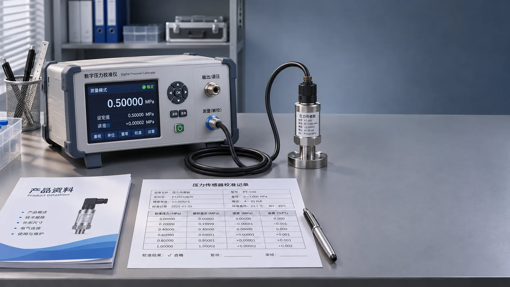
Calibration Tool Specifications: Where to Find and Verify Product Data
Explore product information resources for calibration tools and learn how to verify specifications, certificates and traceability before you buy.

Choosing CE-Marked OEM Tools: Documents Buyers Should Check
Buying OEM tool solutions CE certified for Europe? Discover the documents to check, avoid costly compliance gaps, and choose suppliers with confidence.
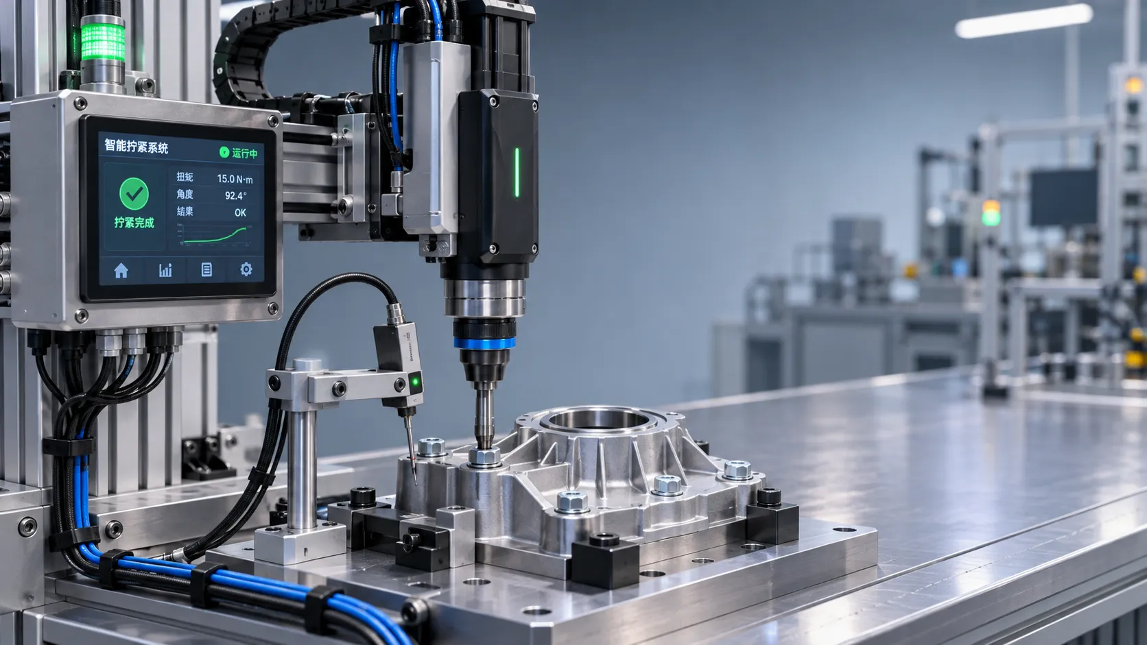
Industrial Innovation Trends: Where Manufacturers Should Invest
Explore industrial innovation trends in fastening, metrology, laser welding, and connected tools—and discover where manufacturers should invest.
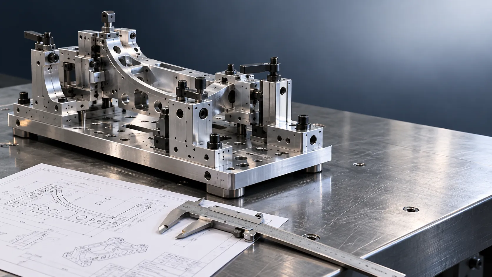
AMS Specifications for Aerospace Tooling: What Do They Cover?
Aerospace tools AMS requirements can cover materials, processes and documentation. Learn how to verify compliance and assess finished-tool acceptance.

Choosing Industrial Assembly Solutions for High-Mix Production Lines
Choose industrial assembly solutions for high-mix production with practical guidance on changeovers, quality, traceability, automation, and total cost.
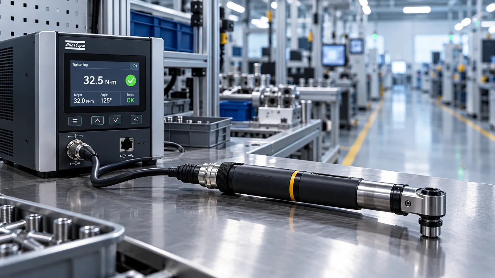
Choosing an Industrial IoT Tools Distributor: Integration and Support Criteria
Choose an industrial IoT tools distributor with confidence. Compare integration, support, security, and lifetime costs to avoid hidden risks and protect production.
What Does GPTWM Mean? How to Verify Its Meaning in Context
What does gptwm mean? Explore its industrial context and learn how to verify the full name, publisher, and supporting sources before relying on its claims.

Industrial AI Compliance Guide: What to Check Before Factory Deployment
Use this industrial intelligence compliance guide to check safety, legal duties, cybersecurity, and validation before factory AI deployment. Explore the checklist to close critical gaps.
Choosing a Laser Welding Equipment Supplier: Weld Trials, Warranty, and Support
Choosing a laser welding equipment supplier? Learn how to verify weld trials, compare warranty coverage, and assess support to reduce downtime and buy with confidence.
Related News
- 00
0000-00
Calibration Tool Specifications: Where to Find and Verify Product Data - 00
0000-00
Industrial Assembly Specifications: How to Define Tolerances and Torque - 00
0000-00
AMS Specifications for Aerospace Tooling: What Do They Cover? - 00
0000-00
Choosing Industrial Assembly Solutions for High-Mix Production Lines - 00
0000-00
Industrial AI Compliance Guide: What to Check Before Factory Deployment
0000-00
Prof. Marcus Chen
Weekly Insights
Stay ahead with our curated technology reports delivered every Monday.