
How to Select Optical Metrology Solutions for Tight-Tolerance Manufacturing





How to Select Optical Metrology Solutions for Tight-Tolerance Manufacturing
Selecting optical industrial metrology solutions for tight-tolerance manufacturing is not a matter of choosing the instrument with the smallest stated accuracy value. A system can perform well in a controlled demonstration and still create unreliable inspection decisions when parts arrive warm from machining, surfaces are highly reflective, operators vary, or production requires results before the next operation begins.
For technical evaluators, the real question is whether a measurement system can make dependable pass/fail and process-control decisions under the conditions in which the factory actually operates. That means looking beyond resolution and nominal point accuracy toward repeatability, uncertainty, surface response, part fixturing, cycle time, software workflow, data traceability, and the ability to maintain performance over time.
Optical methods can be exceptionally capable for complex geometry, freeform surfaces, weld features, thin-walled parts, and components that are difficult to inspect by contact. But “optical” is not one technology category with one set of strengths. Structured-light systems, laser line scanners, vision measurement systems, photogrammetry-assisted workflows, confocal sensors, and laser triangulation sensors each make different trade-offs. A sound selection process starts with the part and the decision to be made, not with a preferred scanner format.
Start with the inspection decision, not the instrument specification
Tight tolerance does not automatically mean that every feature requires the same measurement technology. A housing may have freeform external surfaces suited to optical scanning, while a functional bore, datum face, or internal thread still calls for a different method. The objective is not to force one system to inspect the entire component. It is to build a measurement strategy that supports the critical manufacturing decisions with the least avoidable uncertainty and delay.
Before comparing suppliers, define which decision the measurement must support. Is the system intended for first-article inspection, tool tryout, in-process adjustment, final quality release, reverse engineering, supplier verification, or root-cause analysis? A system used to diagnose a dimensional drift can tolerate a different workflow from one used to automatically reject parts on a high-volume line. Confusing these use cases often leads to a costly mismatch: either an over-engineered laboratory system on the shop floor or a fast production sensor being asked to provide metrology-lab confidence.
The tolerance itself should be reviewed in context. A drawing tolerance is not a complete measurement requirement. Evaluators need to identify the feature type, datum scheme, functional relationship, allowable form error, surface condition, inspection frequency, and risk if a false acceptance or false rejection occurs. Geometric dimensioning and tolerancing requirements can be especially revealing, because a deviation map of a scanned surface is not automatically equivalent to a valid datum-based evaluation.
Translate part conditions into technology requirements
Optical measurement is strongly influenced by the way light interacts with the surface. Matte machined aluminum, dark rubber, polished tool steel, transparent plastic, rough castings, and freshly welded assemblies may all demand different exposure settings, scanning angles, filtering approaches, or surface preparation. A system that handles one material well should not be assumed to perform equally well on another.
Reflective and highly polished surfaces are a familiar concern. They may produce glare, missing data, or unstable edge definition. Dark surfaces may return limited signal, while translucent materials can allow light to scatter below the visible surface. Temporary matte coating can help in some applications, but it changes the workflow and may be unacceptable for clean-room, medical, aerospace, or customer-sensitive parts. If coatings are not permitted, that condition should be included in the evaluation from the beginning rather than treated as a later exception.
Access is equally important. Optical systems see only what their cameras or sensors can see. Deep pockets, steep walls, narrow gaps, undercuts, bores, and occluded interfaces can create blind areas. Multi-angle scanning, rotary fixtures, robot motion, or supplementary probing may address some of these issues, but each addition affects setup time, programming effort, calibration discipline, and uncertainty. A digital model that appears fully measurable on screen may hide sight-line constraints that become obvious only when the real part is fixtured.
The part’s thermal state deserves early attention
In tight-tolerance work, thermal behavior can matter as much as sensor capability. A part measured directly after machining, grinding, welding, or heat treatment may not be at the temperature assumed by its drawing or inspection procedure. The part, fixture, sensor, and surrounding air can all contribute to variation. Optical systems may acquire data quickly, but fast acquisition does not eliminate thermal expansion or distortion.
This is particularly relevant for large assemblies and welded structures. Local heat input can change geometry in ways that are meaningful for fit-up even when the overall part appears dimensionally acceptable. For such work, evaluators should distinguish between a measurement intended to describe the as-built state and one intended to verify conformance under a defined reference condition. Those are not always the same task.
Assess measurement performance as a complete system
Supplier literature often highlights point spacing, resolution, or a single accuracy statement. These values are useful, but none should be read in isolation. Resolution describes how finely data may be sampled; it does not prove that the system can accurately determine a feature or make a reliable tolerance decision. A dense point cloud can still contain systematic error, noise, poor registration, or edge artifacts.
A stronger evaluation asks for evidence of performance on representative parts, materials, feature sizes, and measurement volumes. Repeatability matters because production decisions depend on whether the same part produces consistent results across repeated scans. Reproducibility matters when shifts, operators, fixtures, or stations change. If the application will support capability studies or automated acceptance, the organization should define an appropriate measurement-system analysis plan with its quality team rather than relying on a generic demonstration report.
Registration is another point that deserves scrutiny. Many optical workflows combine multiple views into one coordinate system. The registration method—targets, fixtures, geometry-based alignment, photogrammetry, or a combination—affects both operational convenience and result confidence. A quick best-fit alignment can be useful for diagnosing overall shape, yet it may conceal a functional datum shift. For acceptance inspection, the alignment strategy must match the drawing intent and be controlled in the inspection program.
Do not underestimate fixturing, automation, and human factors
In many projects, the sensor is not the limiting factor. The limiting factor is how consistently the part is presented to it. A handheld scanner may be an excellent choice for flexible inspection, rework analysis, or low-volume complex parts, but its results can depend on operator path, coverage, line of sight, and use of targets. A fixed automated cell can reduce variation and improve cycle consistency, yet it requires disciplined fixturing, safeguarding, maintenance, and a realistic response plan when the robot or part position changes.
Automation readiness should therefore be evaluated as a process question. Is the part location repeatable enough? Can the component be loaded safely without damaging reference surfaces? Are there multiple part variants, and how will the system identify them? Will the station need to operate around coolant mist, vibration, ambient-light variation, welding residue, or dust? These details determine whether an optical inspection cell becomes a reliable control point or a source of frequent exceptions.
Ergonomics also affects measurement quality. If operators must repeatedly reposition heavy parts, apply coating, reach around fixtures, or interpret complex alignment choices, variation tends to enter the workflow. A simpler program with clear prompts and controlled decision paths may be more valuable than a feature-rich interface that only a metrology specialist can use confidently.
Software is where data becomes an inspection decision
Optical industrial metrology solutions generate substantial data, but a point cloud alone does not close the quality loop. The software must turn acquired data into feature evaluations, deviation analysis, reports, and actionable feedback without introducing uncontrolled interpretation. Technical evaluators should examine how the platform imports nominal CAD, handles datum alignment, creates inspection routines, applies tolerances, and records exceptions.
Interoperability matters where inspection connects to manufacturing execution, statistical process control, product lifecycle management, or customer reporting systems. There is no universal integration requirement, but teams should clarify export formats, API availability where relevant, user-permission controls, revision management, and whether raw measurement data can be retained independently of a proprietary reporting view. Long-term access to data becomes important when a quality dispute or process investigation occurs months later.
The most useful reporting output is usually not the most colorful one. A production engineer may need a concise trend on a critical profile or gap. A quality engineer may need traceable feature values tied to a drawing revision. A tooling team may need a full surface comparison to locate distortion. One system can support all three, but only if templates and workflows are designed around the decisions each user must make.
Run a representative acceptance trial before committing
A meaningful trial should include parts that reflect normal variation, not only a clean nominal sample. If practical, include the challenging surfaces, tightest features, expected production fixtures, and actual operator workflow. Define the evaluation criteria in advance: required coverage, feature results, repeat scans, acceptable cycle time, reporting format, setup burden, and limitations that must be documented. The trial should also show what happens when data is incomplete, a part is misloaded, or the surface condition changes.
This approach protects both buyer and supplier. It replaces broad claims with a shared understanding of what the solution can measure reliably, what requires a secondary method, and what process controls must be in place. When tolerances are extremely demanding, the evaluation may need input from metrology specialists and a formal uncertainty review under the organization’s applicable quality framework.
Choose for the manufacturing loop you need to control
The right optical solution is the one that produces trustworthy information quickly enough to influence the process, while preserving the traceability required for the decision. It may be a portable scanner for weld distortion assessment, a vision system for repeatable small-part features, an automated laser scanning cell for high-volume geometry, or a hybrid workflow that combines optical coverage with tactile verification of selected functional dimensions.
At The Global Precision Tools & Welding Matrix, the recurring lesson across industrial assembly, metal joining, and precision metrology is that the final manufacturing mile exposes every weak assumption. Technology selection should connect sensor performance to material behavior, operator practice, data governance, and the economics of rework or delayed decisions. That is where metrology becomes more than inspection: it becomes a disciplined source of manufacturing intelligence.
Before approving a purchase, document the critical features, surfaces, datum strategy, environmental conditions, required cycle time, integration needs, and evidence expected from the acceptance trial. If any of those items remains vague, the equipment comparison is premature. Precision tools deliver their full value when the measurement plan is as carefully engineered as the part itself.
Related News
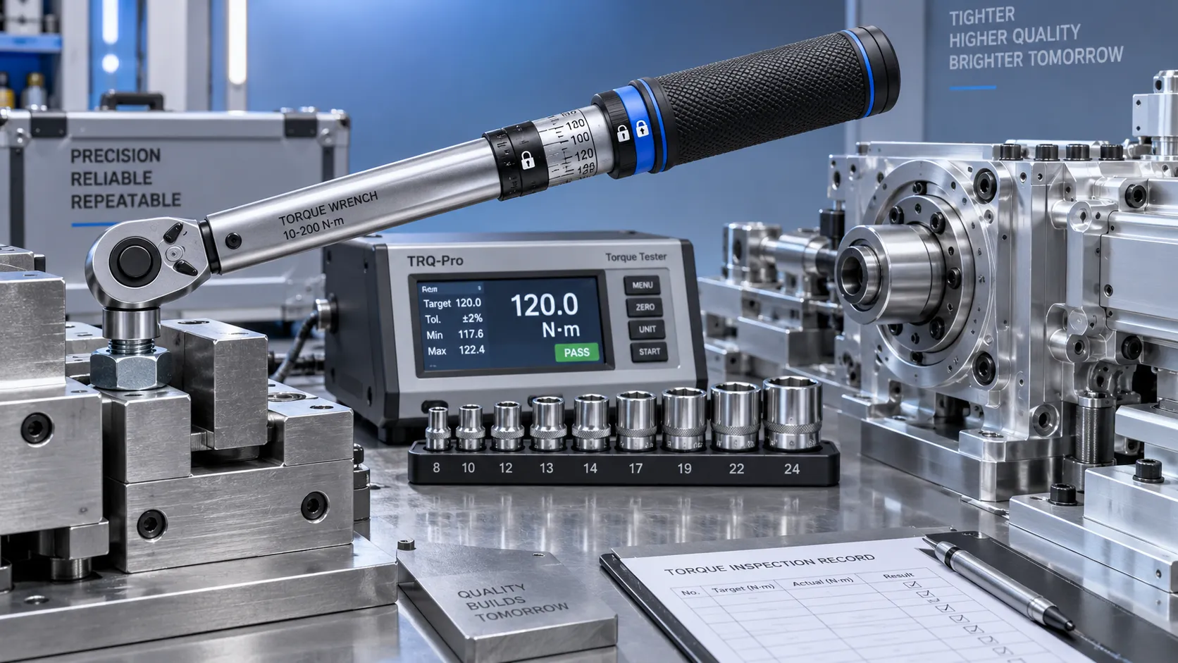
Selecting Adjustable Torque Tools for Repeatable Fastener Assembly
Adjustable torque tools: learn how to match range, accuracy, control methods, calibration, and ergonomics for repeatable, reliable fastener assembly.

How to Select Aerospace Inspection Tools for Aircraft Maintenance Tasks
Aerospace maintenance inspection tools: learn how to select reliable, traceable equipment for aircraft access, accuracy, calibration, and compliant maintenance decisions.

How to Select Wire Bonding Tools for Fine-Pitch Semiconductor Packaging
Explore semiconductor manufacturing tools for wire bonding and learn how to select precision solutions for fine-pitch packaging, reliable loops, accuracy, and yield.
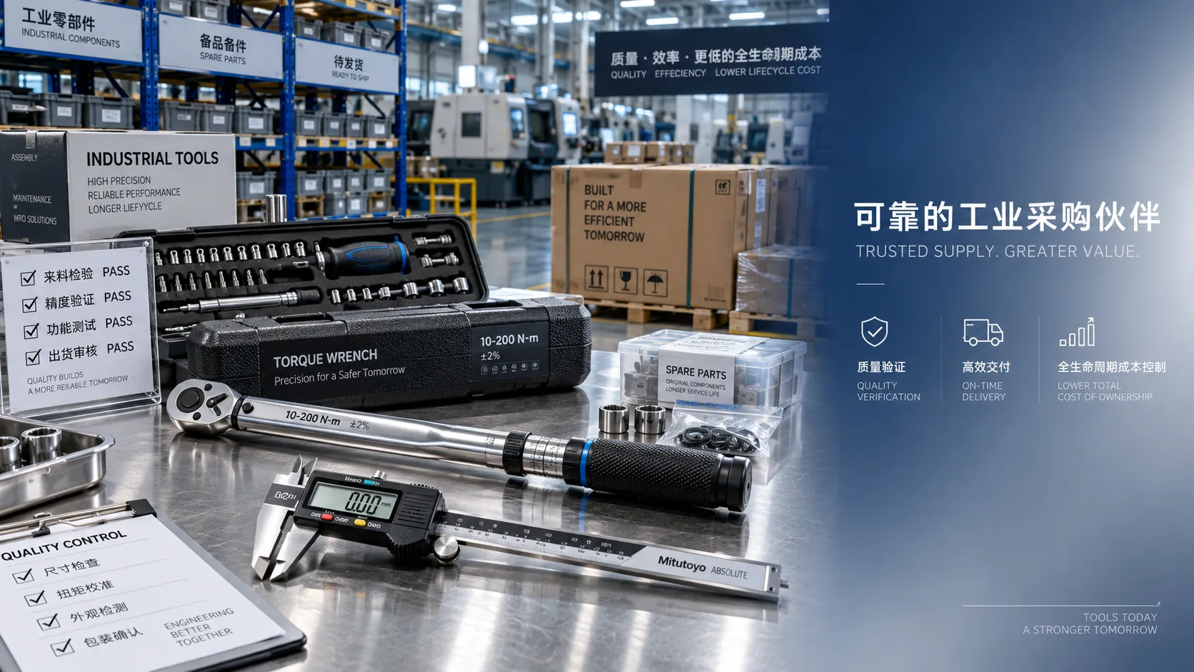
How to Compare Industrial Tool Suppliers for Quality, Lead Time, and Total Cost
Industrial tool selection supplier comparison made simple: evaluate quality, lead times, total cost, service, and supply resilience for confident sourcing decisions.
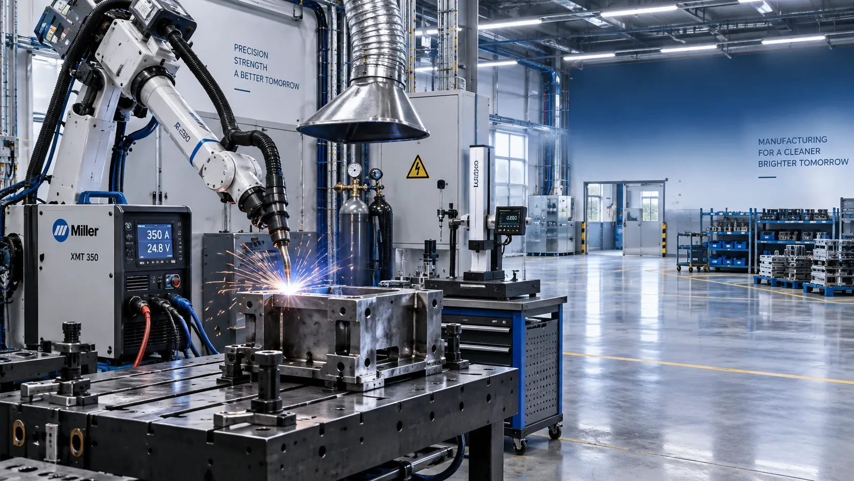
Industrial Equipment Application Guidance: Match Machines to Operating Conditions
Application guidance industrial equipment: match capacity, duty cycle, materials, site conditions, safety, and lifecycle cost to improve reliable output. Read the guide.
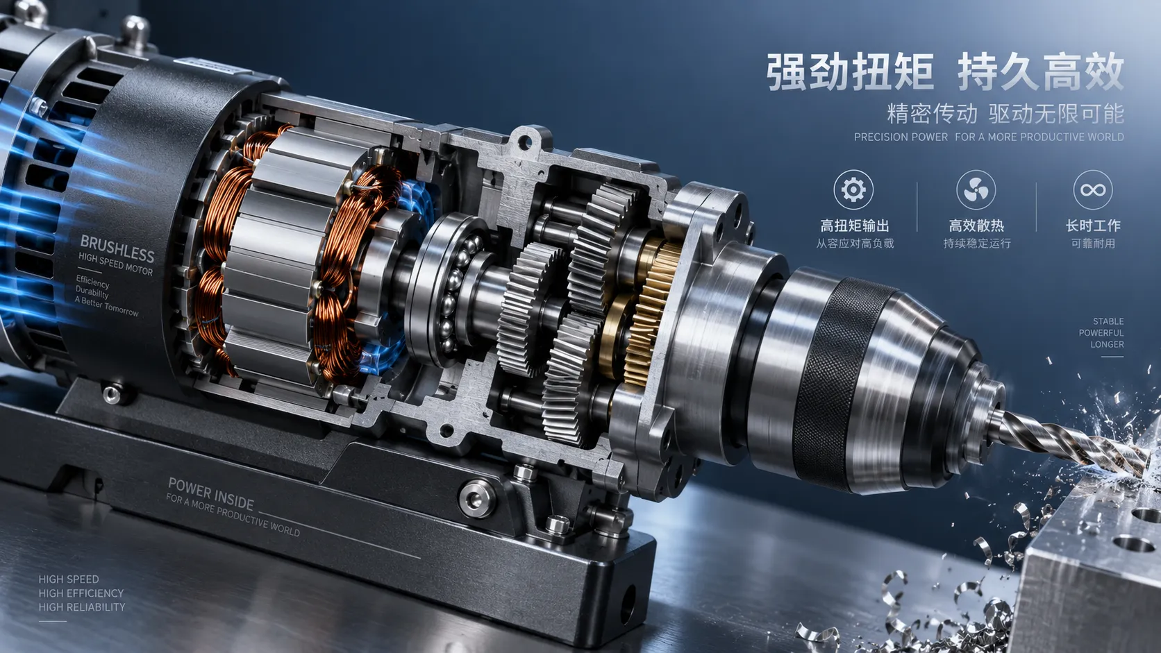
Selecting High-Speed Brushless Tool Motors for Torque, Heat, and Duty Cycle
High speed brushless tool motors: learn how to balance torque, heat, gearing, and duty cycle for reliable industrial tool performance and longer service life.
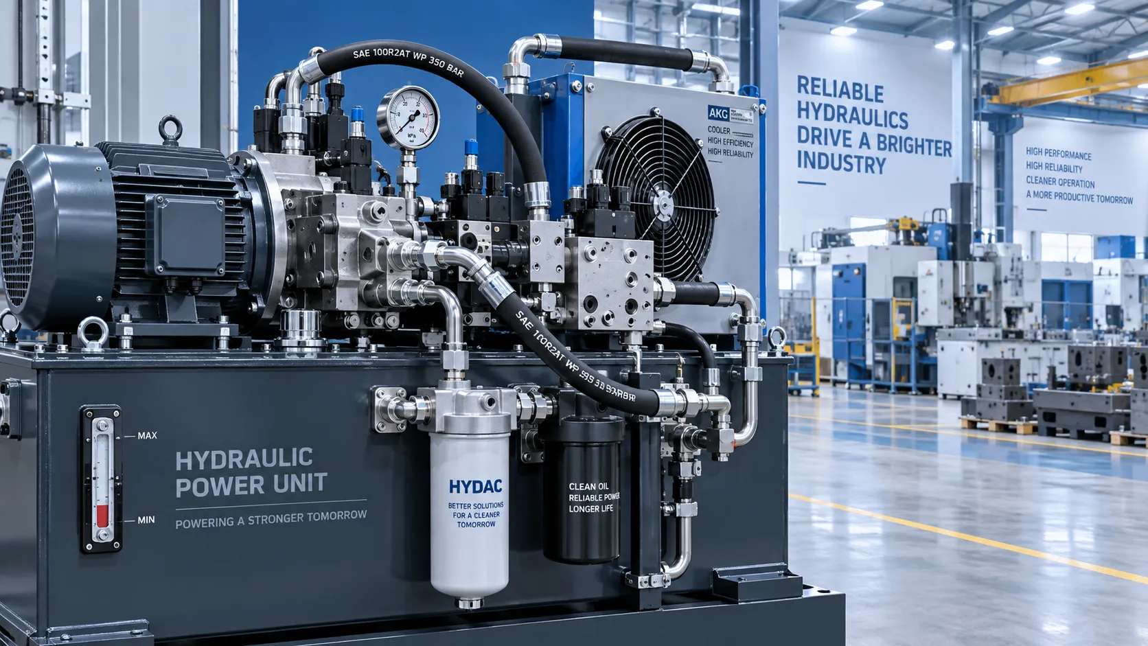
What Determines Industrial Hydraulic System Price for Heavy-Duty Equipment?
Industrial hydraulic system price depends on duty cycle, pressure, components, cooling, and integration. Compare quotes intelligently to secure reliable heavy-duty performance.
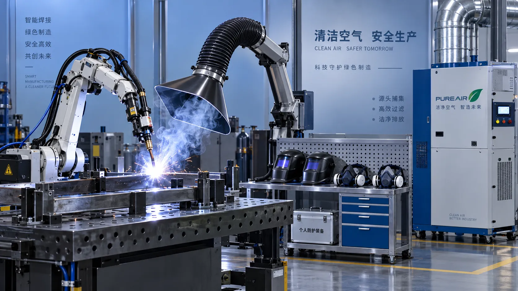
Welding Fume Extraction PPE: When Respirators Are Not Enough for Shop Safety
Welding fume extraction PPE: learn why respirators alone fall short and how source capture, ventilation, and layered controls improve shop safety.

Ergonomic Standards for Assembly Workstations: A Practical Compliance Checklist
Ergonomic standards assembly checklist for safer, compliant workstations—optimize posture, reach, tools, manual handling, lighting, and repetition while supporting quality and productivity.
Related News
- 00
0000-00
Selecting Adjustable Torque Tools for Repeatable Fastener Assembly - 00
0000-00
How to Select Aerospace Inspection Tools for Aircraft Maintenance Tasks - 00
0000-00
How to Select Wire Bonding Tools for Fine-Pitch Semiconductor Packaging - 00
0000-00
Industrial Equipment Application Guidance: Match Machines to Operating Conditions - 00
0000-00
Selecting High-Speed Brushless Tool Motors for Torque, Heat, and Duty Cycle
Prof. Marcus Chen
Weekly Insights
Stay ahead with our curated technology reports delivered every Monday.