
Selecting High-Speed Brushless Tool Motors for Torque, Heat, and Duty Cycle





Selecting High-Speed Brushless Tool Motors for Torque, Heat, and Duty Cycle
Selecting high speed brushless tool motors requires more than comparing RPM figures. Technical evaluators must balance torque, thermal performance, control strategy, and duty-cycle requirements before approving a platform.
The right motor is the one that delivers required fastening, cutting, grinding, or drilling output throughout the expected work cycle without excessive temperature, unstable control, or premature component wear.
For industrial tools, nominal specifications can look adequate while real performance fails under sustained loads. Evaluation should therefore focus on the complete electromechanical system, not motor speed alone.
This guide explains how technical teams can assess high speed brushless tool motors for assembly, metalworking, and maintenance applications where productivity, repeatability, and service life matter.
What Technical Evaluators Are Actually Trying to Confirm
The core search intent behind high speed brushless tool motors is practical selection. Evaluators want to know whether a motor can meet application load demands reliably, efficiently, and economically.
They are usually comparing motor options for a new tool platform, replacing a legacy brushed design, or investigating field failures involving overheating, weak torque, shortened runtime, or unstable speed.
The most important question is rarely “What is the highest RPM?” Instead, it is “Can this motor maintain useful torque at the required operating speed?”
That distinction matters because a tool can spin freely at impressive speed yet stall, overheat, or trigger controller protection when it encounters a real production load.
Technical evaluators also need confidence that laboratory results translate into factory conditions. Dust, ambient temperature, operator technique, battery voltage sag, and repetitive cycles all affect motor behavior.
A sound selection process links motor capability to the duty cycle, load profile, gearing, cooling path, electronics, and mechanical interface of the finished tool.
Start With the Actual Load Profile, Not the Catalog Rating
Motor selection should begin by describing the work performed at the output spindle or accessory. This includes peak torque, continuous torque, target speed, acceleration demand, and load duration.
A cordless impact driver, angle grinder, drill, and precision screwdriver can all use brushless motors, but their electrical and thermal demands are fundamentally different.
Peak torque is the highest short-duration torque needed to overcome breakaway friction, start a cut, drive a fastener, or recover from a sudden load increase.
Continuous torque is the torque required over a longer interval without exceeding temperature limits. For many industrial tools, continuous torque determines dependable productivity more than peak torque.
Evaluators should obtain a representative load trace whenever possible. A trace shows torque and speed changes over time, revealing whether the application is dominated by bursts, sustained load, or repeated transitions.
Free-speed RPM should not be treated as a performance guarantee. It only describes unloaded rotation and provides limited information about useful output at the working point.
For a torque-sensitive assembly tool, the most valuable data may be torque stability near the target fastening speed. For grinding, it may be speed retention under material contact.
For drilling or cutting, the key issue may be whether the motor avoids prolonged stall conditions while delivering enough torque through the selected gear reduction.
Read the Torque-Speed Curve Before Comparing Maximum RPM
The torque-speed curve is one of the most useful documents for comparing high speed brushless tool motors. It shows how available torque changes as rotational speed increases.
In a simplified DC motor model, torque falls as speed rises because back electromotive force reduces the effective voltage available to drive current through the windings.
Brushless motor behavior is also shaped by controller limits, commutation strategy, battery capability, supply voltage, and current protection settings. These variables must be included in the review.
A motor with a higher no-load speed may produce less torque at the operating point than a lower-speed alternative with more suitable winding resistance, magnet design, or controller calibration.
Ask suppliers for curves measured with the intended voltage, controller, cooling conditions, and gear ratio. Curves generated under ideal bench conditions can be misleading.
Identify the normal operating region rather than selecting near the curve’s limits. A practical design retains margin for worn accessories, harder materials, low battery state, and hot ambient conditions.
Stall torque can be useful as a comparison value, but it is not a safe operating point. Sustained stall produces high current and rapid heat generation.
For production tools, evaluate torque reserve at the required working speed. This is more meaningful than choosing a motor based solely on maximum torque or maximum RPM.
Match Motor Speed to Gearing and the Working Accessory
High rotor speed is often beneficial because it can improve power density. However, the motor must be matched carefully with gearbox reduction and the operating speed of the accessory.
Mechanical output power is the product of torque and speed. A high-speed motor can produce useful tool torque through reduction gearing, provided gearbox efficiency and durability remain acceptable.
Gear reduction increases output torque while reducing spindle speed. It also introduces friction, noise, backlash, bearing loads, and heat that should be assessed with the motor.
For precision fastening tools, gearing must support torque accuracy and repeatability. Excessive backlash or gear compliance can reduce control precision, especially during final seating events.
For grinders and cutting tools, direct drive or low reduction may be preferred. In these cases, rotor balance, bearing quality, overspeed protection, and accessory safety ratings become critical.
Do not choose motor speed independently from the tool head. The required spindle RPM, accessory diameter, cutting surface speed, and gear ratio jointly determine a workable motor-speed range.
High-speed brushless motors also impose greater demands on shaft retention, bearings, fan structures, and rotor containment. Mechanical integrity must match the highest credible overspeed condition.
Thermal Performance Is Usually the Real Design Limit
Heat is the primary reason a motor that performs well in short demonstrations can fail in practical industrial service. Thermal selection deserves more attention than headline power figures.
Motor losses arise mainly from winding resistance, magnetic hysteresis, eddy currents, bearing friction, controller switching, and mechanical transmission losses. These losses convert directly into heat.
Copper loss increases with the square of current. A modest current increase during a difficult task can therefore create a disproportionately large increase in winding temperature.
High speed introduces additional iron and windage losses. A motor optimized for lower rotational speed may become inefficient or thermally unstable when driven beyond its intended range.
Temperature affects magnets, insulation, lubricants, adhesives, electronic components, and bearings. A successful evaluation considers component temperature limits, not merely external housing temperature.
Winding temperature is especially important because insulation degradation accelerates as temperature rises. Repeated overheating may not cause immediate failure, but it can sharply reduce expected service life.
Measure temperatures at realistic ambient conditions and with realistic enclosures. A test performed in a cool laboratory with unrestricted airflow may overstate the tool’s available continuous power.
Thermal imaging is helpful for identifying hotspots, but embedded thermocouples or resistance-based winding measurements provide better evidence of internal thermal stress.
Calculate Duty Cycle as a Thermal Load, Not a Simple Percentage
Duty cycle is often expressed as the percentage of time a tool is active. For motor selection, that definition is incomplete because load intensity and cooling time are equally important.
A tool operating ten seconds every minute at moderate load may remain cool. The same tool operating ten seconds every minute near stall can overheat rapidly.
Technical teams should document run time, pause time, torque level, speed level, number of cycles, ambient temperature, and expected shift duration for each application.
Intermittent service can allow heat to dissipate between cycles, but cooling depends on housing mass, airflow, fan operation, mounting surfaces, and the temperature of surrounding equipment.
Repeated short bursts can be more severe than one continuous run when acceleration currents are high. This is common in fastening tools, robotic stations, and start-stop production processes.
Evaluate the full thermal sequence rather than a single isolated cycle. Motor temperature may continue rising until it reaches equilibrium after dozens or hundreds of repetitions.
A useful test protocol includes cold-start performance, stabilized-temperature performance, and recovery time after peak demand. These results reveal whether protection settings are appropriately calibrated.
When duty cycle is uncertain, select conservatively. Increasing thermal margin is typically less expensive than redesigning a motor, controller, enclosure, and gearbox after field deployment.
Assess the Controller and Motor as One System
A brushless motor cannot be evaluated separately from its electronic controller. The controller determines commutation, current limits, startup behavior, speed regulation, and protective responses.
Sensorless control can reduce component count and improve packaging flexibility. However, it may provide weaker low-speed startup performance when load changes are abrupt or breakaway torque is high.
Hall sensors or encoder feedback can improve low-speed torque control, position awareness, and consistent startup. They are often valuable in controlled fastening and precision assembly applications.
Current limiting protects the battery, controller, and windings, but overly aggressive limits can make a tool feel weak during normal work. Calibration should reflect the actual load profile.
Speed control strategy also matters. Closed-loop regulation can maintain accessory speed under load, but it may increase current demand and heat if control parameters are poorly tuned.
For battery-powered tools, the system must account for voltage sag, battery internal resistance, state of charge, cell temperature, and battery-management-system current restrictions.
For corded tools, supply variation, electromagnetic compatibility, inrush behavior, and controller protection thresholds should be verified under relevant regional electrical standards.
Request system-level test data whenever possible. A motor listed at a certain power level may not achieve that output when paired with a lower-current controller or constrained battery pack.
Choose Efficiency for Runtime, Temperature, and Productivity
Efficiency is not an abstract specification. In a power tool, higher efficiency can extend battery runtime, reduce motor heat, improve sustained output, and lower stress on electronics.
Brushless designs generally eliminate brush friction and commutator wear, but efficiency still varies significantly across winding choices, magnetic circuits, control methods, and operating speeds.
The most useful efficiency value is measured near the normal working point. Peak efficiency at a lightly loaded speed may have little relevance to demanding industrial use.
Compare electrical input power, mechanical output power, current draw, and temperature rise at several representative loads. This produces a more realistic picture than a single efficiency claim.
High efficiency can also enable smaller housings or lower fan requirements. However, compact packaging should not compromise thermal pathways, sealing requirements, or maintenance access.
In high-volume operations, small efficiency improvements can have meaningful operational effects. Reduced recharge frequency, fewer thermal shutdowns, and longer component life can improve overall line availability.
Efficiency should not be used to justify insufficient torque reserve. A highly efficient motor that operates too close to its limit can still produce poor user experience and shortened service life.
Verify Mechanical Durability at High Rotational Speed
High-speed operation increases mechanical risk. Rotor imbalance, bearing preload errors, shaft runout, and weak retention features can create vibration, noise, heat, and premature failures.
Bearings should be selected for both rotational speed and applied radial or axial loads. Accessory imbalance and gear-mesh forces can reduce bearing life substantially.
For grinding, polishing, and cutting tools, rotor balance and spindle runout directly affect operator comfort, surface quality, bearing durability, and compliance with safety requirements.
Dust, metal particles, moisture, and welding-related contamination can enter through cooling paths. Protection measures must balance contamination resistance with the airflow needed for thermal management.
Consider the expected maintenance environment. A motor that performs well in a clean assembly cell may require different sealing, bearings, coatings, or cooling architecture for field service tools.
Noise and vibration testing should be performed under load, not only at free speed. Gear resonance or control-related tonal noise may appear only within certain speed ranges.
Evaluate connectors, wire routing, strain relief, and solder joints as part of durability testing. High vibration and repeated thermal cycling can damage peripheral electrical components before the motor itself fails.
Build a Practical Validation Plan Before Release
A credible validation plan combines analytical review with prototype testing. It should reproduce the most demanding credible use case rather than relying on average operating conditions.
Begin with a requirements matrix listing output torque, speed range, allowable temperature rise, duty cycle, supply conditions, environmental exposure, target service life, and safety constraints.
Then define acceptance criteria for system performance. Examples include minimum speed under load, maximum winding temperature, recovery time, torque repeatability, vibration limits, and protection behavior.
Test multiple production-representative samples because variation in magnets, winding resistance, bearings, controllers, and assembly quality can affect high-speed performance.
Include accelerated tests such as repeated overload cycles, hot ambient operation, low-voltage operation, blocked-rotor protection checks, vibration exposure, and contaminated airflow exposure where relevant.
Field trials should involve skilled users and normal production operators. Their feedback can reveal trigger response, fatigue, thermal discomfort, stall behavior, and handling issues missed by bench testing.
Document failures with current, voltage, speed, torque, and temperature data. Root-cause analysis becomes much faster when the motor, controller, battery, and mechanical load are measured together.
Supplier evaluation should include manufacturing consistency, traceability, engineering support, spare-part availability, and the ability to control future design changes.
Use a Balanced Selection Decision, Not a Single Ranking Metric
There is no universally best brushless motor. The correct choice depends on the tool’s required output, operating environment, user expectations, manufacturing volume, and allowable system cost.
A compact high-speed motor may be ideal for a lightweight intermittent tool. A larger motor with greater thermal mass may be better for sustained metalworking or repeated industrial cycles.
For assembly applications, prioritize controllable torque, repeatable speed, low-speed behavior, and thermal stability. For abrasive applications, prioritize power density, speed retention, balance, and robust cooling.
For drilling and cutting applications, prioritize torque reserve, overload recovery, gear durability, and control protection. For precision maintenance tools, consider ergonomics, noise, vibration, and serviceability.
Technical evaluators should score alternatives against weighted requirements rather than selecting from a single catalog specification. This makes tradeoffs visible and supports defensible engineering decisions.
Before approval, confirm performance at operating temperature and realistic duty cycle. A motor that meets requirements only when cold or lightly loaded is not ready for industrial deployment.
Conclusion: Select for Sustained Work, Not Impressive Free Speed
The best high speed brushless tool motors deliver the required torque at the required speed while remaining within thermal, electrical, and mechanical limits throughout the intended duty cycle.
For technical evaluators, the most reliable selection method is to start with the real load profile, examine torque-speed behavior, model heat, and validate the complete motor-controller-tool system.
Maximum RPM, peak power, and stall torque are useful reference values, but they should never replace evidence from representative operating conditions and sustained thermal testing.
When torque reserve, cooling capacity, gearing, control strategy, and durability are considered together, brushless tool platforms can achieve stronger productivity, longer service life, and more predictable industrial performance.
Related News
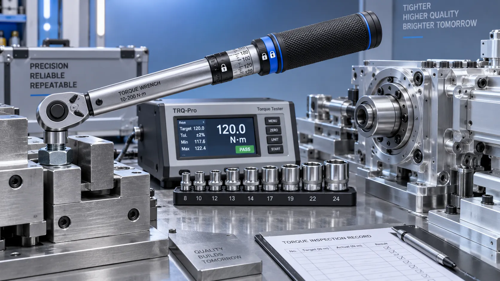
Selecting Adjustable Torque Tools for Repeatable Fastener Assembly
Adjustable torque tools: learn how to match range, accuracy, control methods, calibration, and ergonomics for repeatable, reliable fastener assembly.
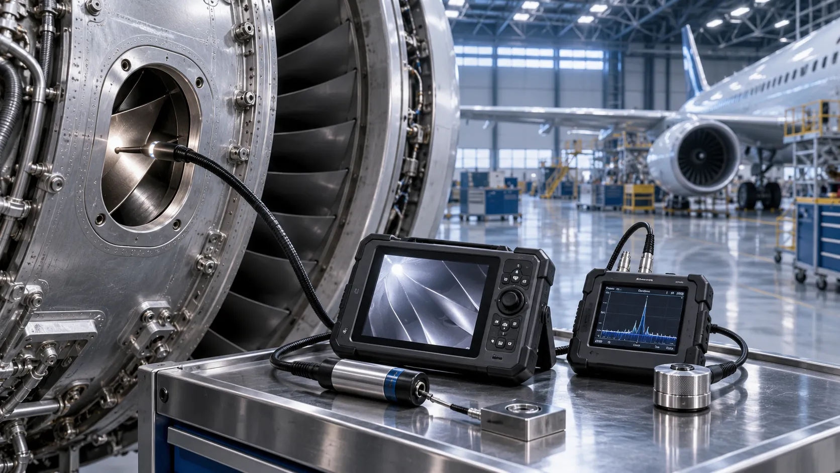
How to Select Aerospace Inspection Tools for Aircraft Maintenance Tasks
Aerospace maintenance inspection tools: learn how to select reliable, traceable equipment for aircraft access, accuracy, calibration, and compliant maintenance decisions.

How to Select Wire Bonding Tools for Fine-Pitch Semiconductor Packaging
Explore semiconductor manufacturing tools for wire bonding and learn how to select precision solutions for fine-pitch packaging, reliable loops, accuracy, and yield.
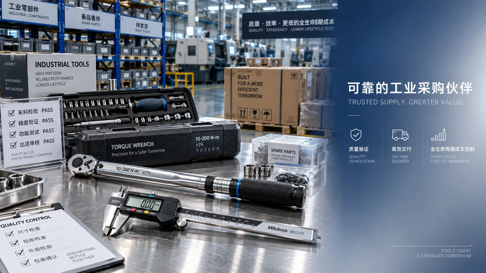
How to Compare Industrial Tool Suppliers for Quality, Lead Time, and Total Cost
Industrial tool selection supplier comparison made simple: evaluate quality, lead times, total cost, service, and supply resilience for confident sourcing decisions.
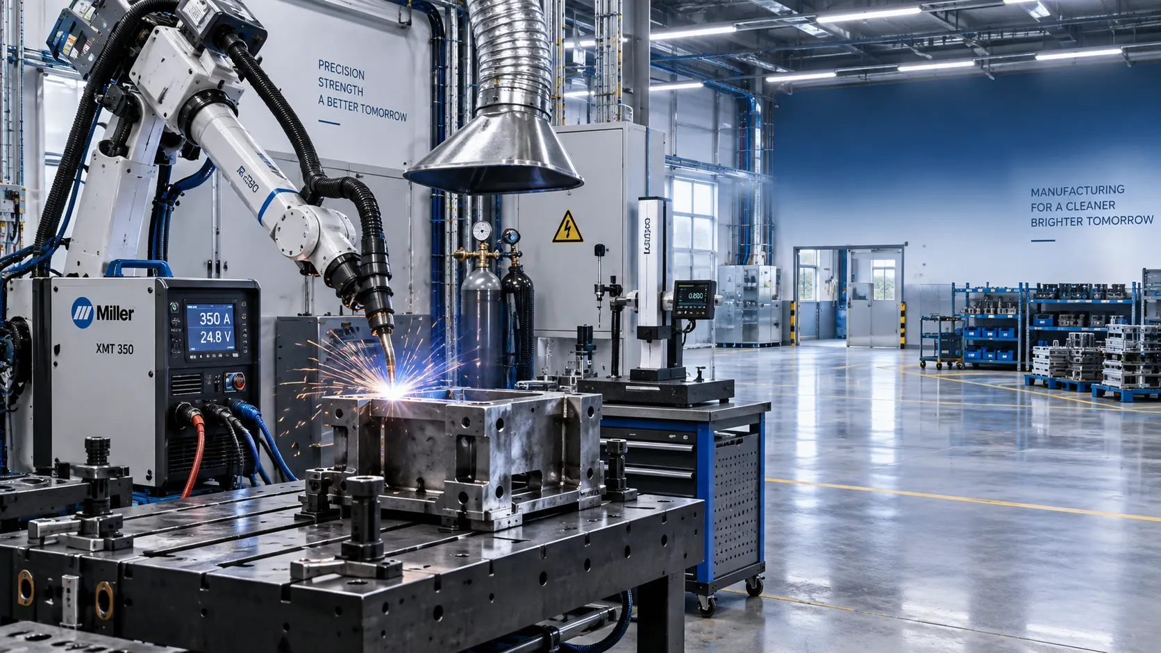
Industrial Equipment Application Guidance: Match Machines to Operating Conditions
Application guidance industrial equipment: match capacity, duty cycle, materials, site conditions, safety, and lifecycle cost to improve reliable output. Read the guide.
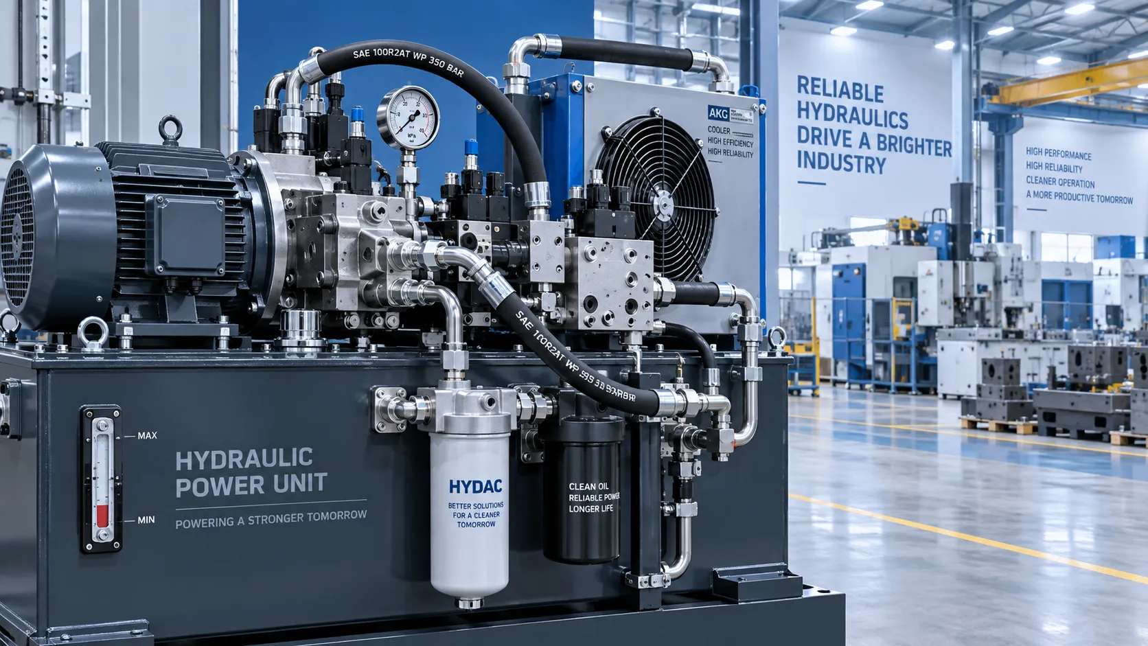
What Determines Industrial Hydraulic System Price for Heavy-Duty Equipment?
Industrial hydraulic system price depends on duty cycle, pressure, components, cooling, and integration. Compare quotes intelligently to secure reliable heavy-duty performance.
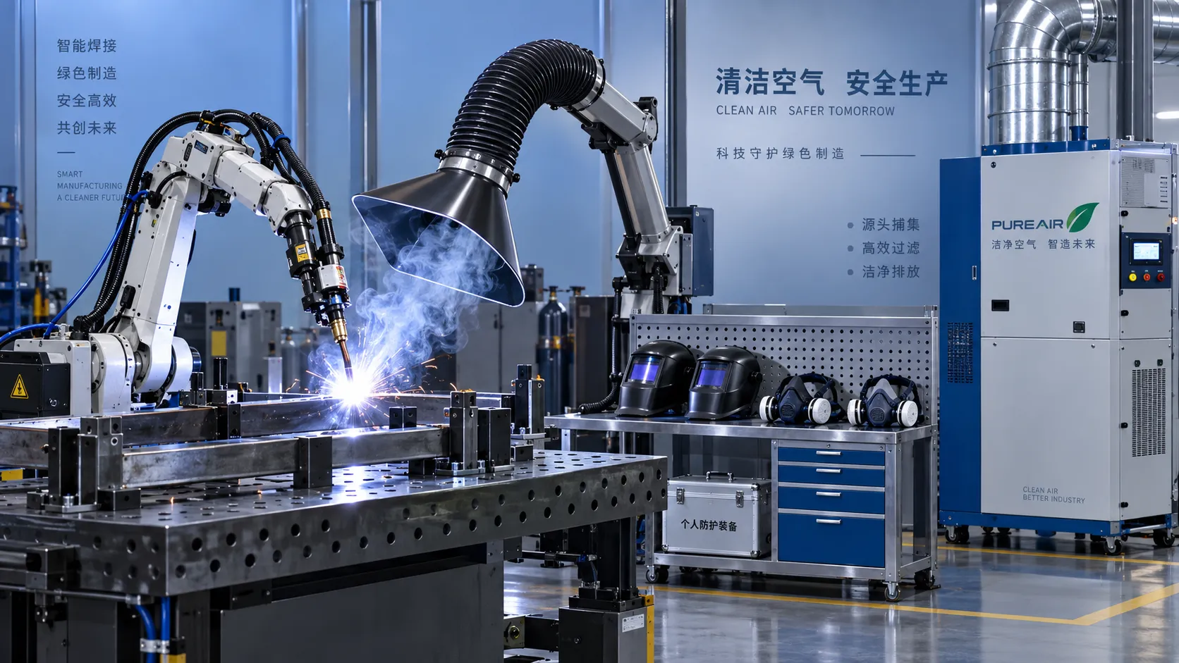
Welding Fume Extraction PPE: When Respirators Are Not Enough for Shop Safety
Welding fume extraction PPE: learn why respirators alone fall short and how source capture, ventilation, and layered controls improve shop safety.
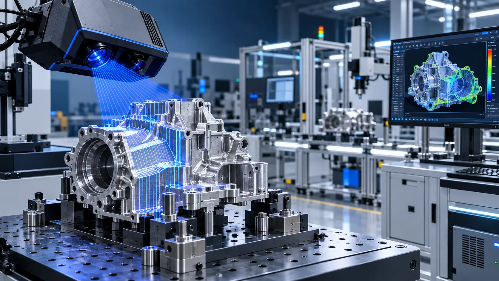
How to Select Optical Metrology Solutions for Tight-Tolerance Manufacturing
Optical industrial metrology solutions for tight-tolerance manufacturing: evaluate accuracy, surface compatibility, workflow, and traceability to select with confidence.

Ergonomic Standards for Assembly Workstations: A Practical Compliance Checklist
Ergonomic standards assembly checklist for safer, compliant workstations—optimize posture, reach, tools, manual handling, lighting, and repetition while supporting quality and productivity.
Related News
- 00
0000-00
Selecting Adjustable Torque Tools for Repeatable Fastener Assembly - 00
0000-00
How to Select Aerospace Inspection Tools for Aircraft Maintenance Tasks - 00
0000-00
How to Select Wire Bonding Tools for Fine-Pitch Semiconductor Packaging - 00
0000-00
Industrial Equipment Application Guidance: Match Machines to Operating Conditions - 00
0000-00
Selecting High-Speed Brushless Tool Motors for Torque, Heat, and Duty Cycle
Prof. Marcus Chen
Weekly Insights
Stay ahead with our curated technology reports delivered every Monday.