
How to Select Wire Bonding Tools for Fine-Pitch Semiconductor Packaging





How to Select Wire Bonding Tools for Fine-Pitch Semiconductor Packaging
Fine-pitch semiconductor packaging leaves very little room for a “good enough” bonding decision. When pad pitch narrows, wire loops become lower, and package density rises, a small variation in tool geometry, clamp behavior, ultrasonic energy, or bond-head alignment can show up later as lifted bonds, pad damage, wire sweep, or difficult-to-explain yield loss.
For technical evaluators, selecting semiconductor manufacturing tools for wire bonding is not simply a matter of comparing machine specifications. The real task is to match a bonding system, bonding tool, wire material, die metallization, and process-control strategy to a specific package architecture. A tool that performs well on a mature leadframe package may be unsuitable for a fine-pitch BGA, QFN, SiP, RF module, or advanced stacked-die assembly.
The most reliable selection process begins with the interconnect requirement rather than the equipment catalog. Before reviewing suppliers, define what must be bonded, how tightly it must be placed, how the bond will be verified, and how much process variation the package can tolerate.
Start with the Bonding Window, Not the Tool Brand
In fine-pitch packaging, the bonding window is the usable range of force, ultrasonic power, time, temperature, and placement accuracy that produces a robust interconnect without damaging the pad or surrounding structures. The smaller that window becomes, the more important the mechanical and control characteristics of the wire bonding tool become.
A practical evaluation should document the following conditions before a tool comparison begins:
- Pad pitch, pad size, and available clearance to neighboring pads or passivation edges
- Bond type: ball bonding, wedge bonding, ribbon bonding, or a mixed interconnect approach
- Wire material and diameter, including gold, copper, palladium-coated copper, silver alloy, or aluminum wire
- Die metallization and leadframe, substrate, or package-side finish
- Required loop profile, wire span, stitch location, and allowable loop height
- Package throughput target and anticipated production volume
- Inspection, pull-test, shear-test, and traceability requirements
This early work prevents a common procurement error: choosing an advanced bonder with impressive published placement accuracy but insufficient force resolution, tool access, or ultrasonic stability for the actual bond stack. Fine-pitch bonding is a system problem. The capillary or wedge, transducer, wire clamp, vision system, heated workholder, motion stage, and recipe software must behave as one controlled process.
Ball Bonding or Wedge Bonding: Let the Package Geometry Decide
Ball bonding remains widely used for high-volume semiconductor assembly because it supports fast cycle times and flexible looping. A capillary forms the free-air ball, places the first bond on the die pad, then creates the second bond on the lead, substrate, or interposer. It is often the preferred route for gold and copper wire applications where dense I/O counts must be handled efficiently.
Yet ball bonding is not automatically the answer for every fine-pitch design. The first bond footprint, capillary access angle, and loop trajectory must be compatible with the die layout. On extremely tight pad arrays or delicate metallization, evaluators should examine whether the ball size and deformation profile leave adequate margin around the pad edge.
Wedge bonding is frequently considered when aluminum wire, low-loop profiles, RF performance, or specialized substrate access is important. It can offer advantages in certain power devices, microwave modules, sensors, and applications where ribbon bonding is needed. However, wedge bonding often imposes directional considerations and may require more careful planning around bond orientation and tool approach.
The decision should be based on actual package constraints, not habit. Ask for representative bond trials using your die, substrate, wire, and intended loop program. A generic demonstration on a supplier’s test vehicle is useful, but it does not establish process capability for your production design.
The Bonding Tool Itself: Geometry Matters at Fine Pitch
When evaluators say “wire bonding tool,” they may mean the complete bonding platform, but the consumable bonding interface deserves equal attention. In ball bonding, this is generally the capillary; in wedge or ribbon bonding, it is the wedge tool. At fine pitch, the shape of this component directly affects bond placement, deformation, wire handling, and access to crowded bond sites.
For capillaries, assess parameters such as tip diameter, chamfer geometry, hole diameter, face angle, and working-face dimensions. These features influence the free-air ball relationship, the contact footprint, wire centering, and the ability to form a stable stitch bond. A capillary designed for a larger pad may produce an overly broad bond footprint when moved into a finer-pitch application. Conversely, an excessively small tool can restrict process latitude and wear more quickly.
For wedge tools, consider the foot geometry, wire channel, feed angle, and access around nearby components. The tool must make consistent contact without clipping adjacent wires, package walls, die edges, or raised features. In advanced assemblies, an apparently minor clearance conflict can force a different bonding sequence, which then changes wire-crossing risk and cycle time.
Tool wear should be treated as a process-control issue rather than a maintenance afterthought. As a capillary or wedge wears, bond dimensions and energy transfer can shift gradually. That drift may remain invisible until pull-test trends, visual inspection failures, or electrical test escapes appear. Define a replacement strategy based on verified process behavior, not only on a fixed number of bonds.
Force Resolution and Ultrasonic Control Are Core Selection Criteria
Fine-pitch pads do not forgive unstable energy delivery. Too little ultrasonic energy can create weak intermetallic contact or inconsistent stitch bonds. Too much energy, especially combined with excessive force, can damage pad metallization, crack brittle dielectric layers, or create bond cratering beneath the pad.
The wire bonder should provide repeatable, controllable bonding force across the range required by the application. Technical teams should look beyond maximum force ratings and ask about low-force stability, force calibration practices, bond-head response, and control-loop behavior during rapid production cycling. A machine built for heavier wire or power-semiconductor applications may not offer the delicacy needed for sensitive fine-pitch die.
Ultrasonic performance also deserves a closer review than a headline frequency specification. Useful questions include:
- How consistently does the system regulate ultrasonic amplitude from bond to bond?
- Can the process recipe independently tune first-bond and second-bond energy profiles?
- How are transducer condition, horn integrity, and tool mounting verified?
- Does the equipment provide alarms or trend data that reveal energy drift?
- Can the platform support process development for both current and future wire materials?
Copper wire illustrates why this matters. It can offer cost and performance benefits, but its harder material behavior can narrow the acceptable process window compared with traditional gold wire. It may demand tighter control of forming gas, free-air-ball consistency, capillary condition, ultrasonic settings, and bonding force. The right equipment is therefore not merely “copper capable”; it should allow engineers to establish and sustain a repeatable copper bonding process.
Accuracy Is More Than XY Placement
Supplier literature often highlights XY accuracy and repeatability. Those figures matter, but they are only one part of fine-pitch bonding accuracy. Real-world placement is influenced by vision recognition, die presentation, substrate flatness, thermal expansion, Z-axis behavior, capillary runout, workholder stability, and motion synchronization.
A strong evaluation examines the full alignment chain. Can the vision system reliably recognize pads with varying reflectivity? How does it manage surface contamination, minor die rotation, or leadframe variation? Is there automatic compensation for substrate distortion or panel-level positional drift? Can operators review image quality and alignment exceptions rather than simply accepting a pass/fail result?
For packages with very small pads, verify that the machine’s camera magnification, lighting options, and pattern-recognition software are suitable for the actual metallization surface. Bright, clean test samples often look easy. Production samples may include oxidation, flux residues, uneven plating, or contrast changes that challenge recognition routines.
Loop Control Becomes a Reliability Decision
Fine-pitch packaging is increasingly shaped by low-profile assemblies, stacked die, molded structures, and dense routing paths. In this environment, wire loop control is not cosmetic. A loop that is slightly too high can interfere with molding flow, encapsulant clearance, lid placement, or neighboring wires. A loop that is too low may risk wire sweep, sag, shorting, or stress concentration near the heel.
Evaluate whether the bonder supports programmable loop profiles rather than a limited set of standard trajectories. The process team should be able to control reverse motion, kink position, wire-feed behavior, and loop height with enough resolution to protect clearance margins. This is particularly important where wire lengths vary across a die or where different bond rows require different approaches.
Ask to see loop repeatability data across multiple units and through a meaningful production run. One attractive loop on a demonstration sample does not prove that the machine can maintain profile consistency after tool changes, temperature shifts, or long operating periods.
Automation Readiness Should Match the Factory Roadmap
A manually loaded bonder can be appropriate for development, specialized modules, and low-volume production. But when the program moves toward scale, the cost of handling variation, recipe transfer, and inspection gaps becomes much clearer. Fine-pitch packages amplify these issues because there is less margin for loading errors and fewer opportunities for rework.
When comparing semiconductor manufacturing tools for wire bonding, review automation as a staged capability. Relevant features may include automatic wire threading, capillary or wedge change support, barcode-based lot control, recipe access management, material handling interfaces, statistical process control connectivity, and integration with automated optical inspection or manufacturing execution systems.
Data availability is especially valuable. Bond-force records, ultrasonic trends, vision offsets, tool-life history, alarm logs, and quality-test results can help engineers distinguish a material issue from an equipment issue before yield loss spreads. GPTWM’s industrial intelligence coverage consistently points to this wider shift: precision tools are increasingly judged not only by mechanical performance, but by how effectively they contribute usable process information to a connected factory.
Build the Evaluation Around Representative Trials
A disciplined trial plan is more informative than a long feature checklist. Request trials that reflect your package’s difficult conditions: the smallest pad, longest wire span, most challenging bond angle, tightest clearance, and intended production wire. Include fresh tools and controlled wear states if possible. The goal is to understand process margin, not simply to demonstrate that a bond can be made once.
Assess visual bond quality, ball or wedge dimensions, pull strength, shear behavior, loop consistency, placement offset, non-stick-on-pad rate, and signs of pad damage. Reliability testing should be aligned with the package’s application environment, whether that involves thermal cycling, humidity exposure, vibration, high-frequency operation, or extended power cycling.
During the trial, pay attention to setup time and recipe usability. A technically capable platform can still create operational risk if process transfer between shifts, sites, or product variants depends on a single experienced engineer. Clear parameter control, user permissions, calibration records, and repeatable changeover procedures are part of the tool’s real value.
Questions That Reveal a Better Supplier Fit
Technical evaluators should expect a supplier to discuss limitations openly. Useful questions include: Which tool geometry is recommended for this pad and wire combination, and why? What failure modes have appeared in comparable applications? Which settings are most sensitive during process qualification? How is long-term accuracy calibrated? What local support is available for transducer, vision, motion, and consumable-tool issues?
Also examine the supply path for capillaries, wedges, spare parts, software updates, and service expertise. A finely tuned bonding process can be disrupted by inconsistent consumable availability or slow technical response. The lowest acquisition cost may become expensive if production teams cannot sustain the process over the tool’s lifecycle.
A Selection Decision That Holds Up Beyond Qualification
The best wire bonding choice is rarely the machine with the longest feature list. It is the combination of bonder, bonding tool, wire, process recipe, and support model that delivers a stable bonding window for the package now while leaving enough flexibility for the next design revision.
For fine-pitch semiconductor packaging, prioritize controlled low-force bonding, stable ultrasonic delivery, appropriate capillary or wedge geometry, dependable vision alignment, programmable loop formation, and traceable process data. Then prove those capabilities with representative trials and reliability evidence. This approach gives technical evaluators a firmer basis for selecting wire bonding tools—and protects the interconnect quality on which the entire package depends.
Related News
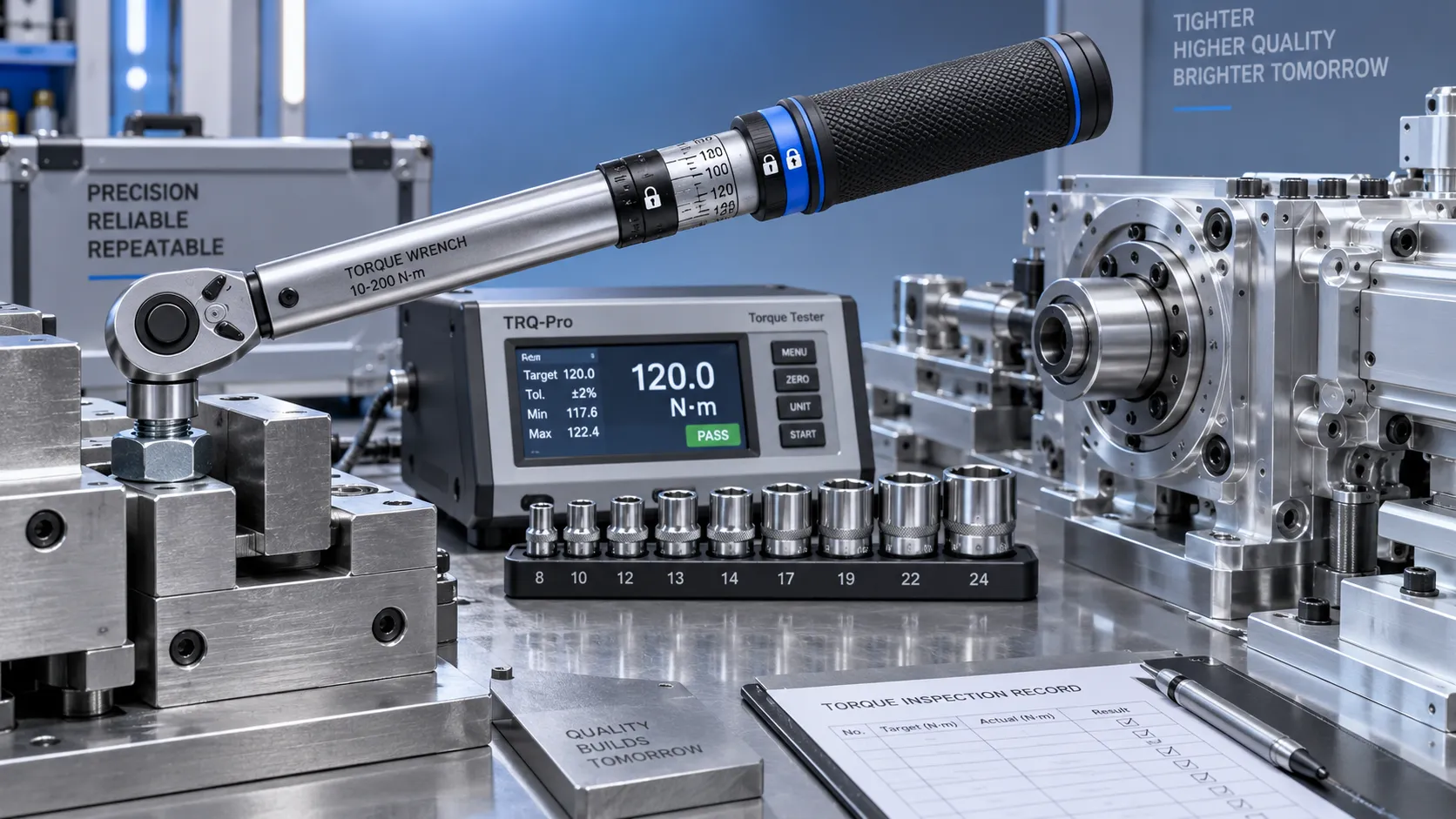
Selecting Adjustable Torque Tools for Repeatable Fastener Assembly
Adjustable torque tools: learn how to match range, accuracy, control methods, calibration, and ergonomics for repeatable, reliable fastener assembly.
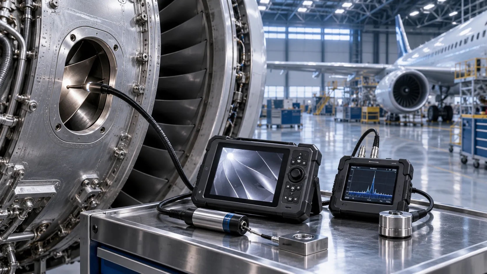
How to Select Aerospace Inspection Tools for Aircraft Maintenance Tasks
Aerospace maintenance inspection tools: learn how to select reliable, traceable equipment for aircraft access, accuracy, calibration, and compliant maintenance decisions.
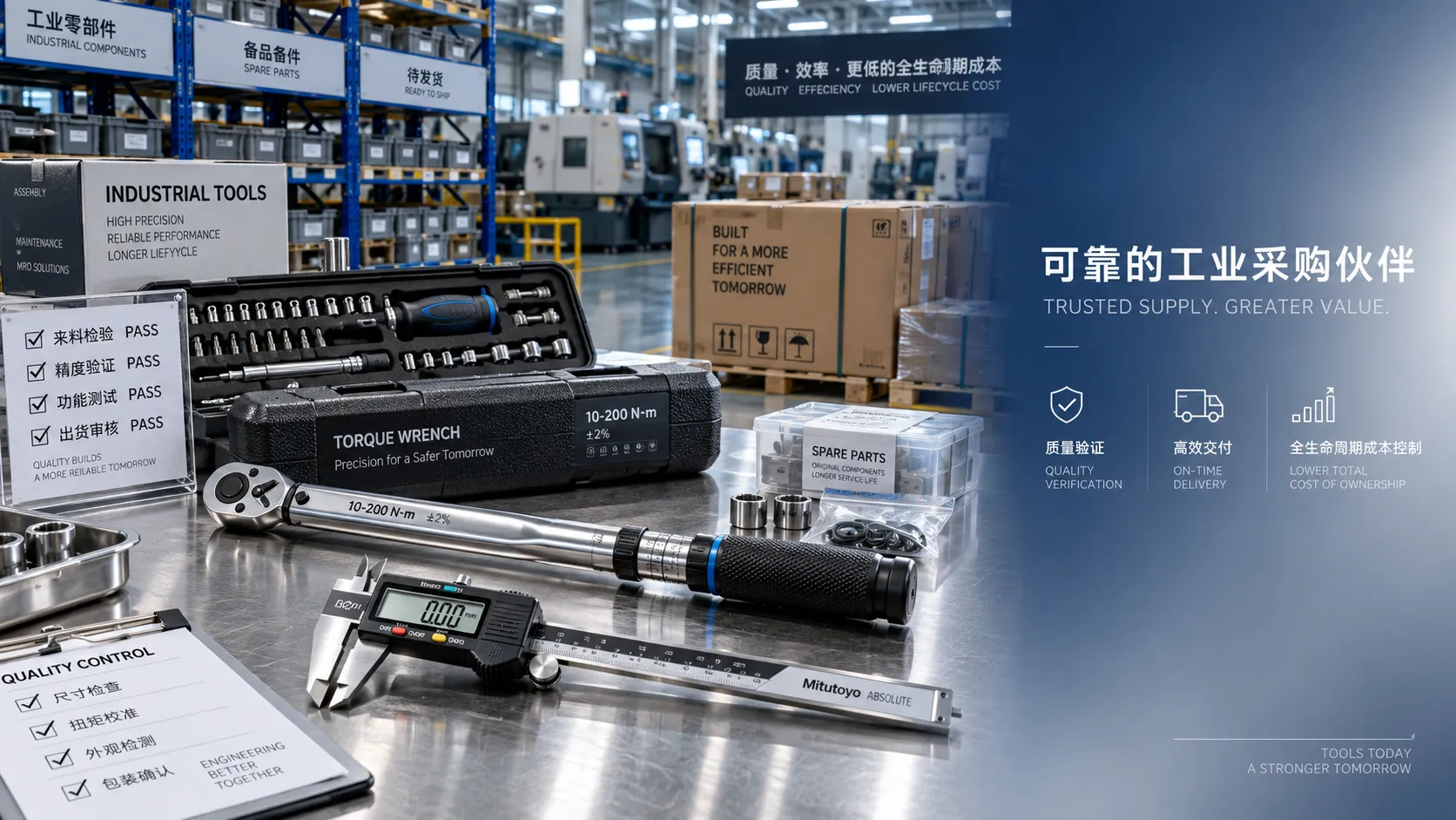
How to Compare Industrial Tool Suppliers for Quality, Lead Time, and Total Cost
Industrial tool selection supplier comparison made simple: evaluate quality, lead times, total cost, service, and supply resilience for confident sourcing decisions.
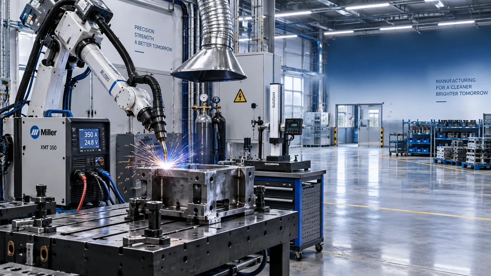
Industrial Equipment Application Guidance: Match Machines to Operating Conditions
Application guidance industrial equipment: match capacity, duty cycle, materials, site conditions, safety, and lifecycle cost to improve reliable output. Read the guide.
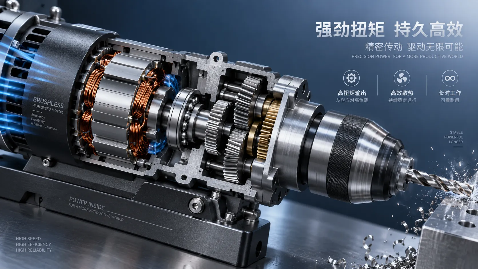
Selecting High-Speed Brushless Tool Motors for Torque, Heat, and Duty Cycle
High speed brushless tool motors: learn how to balance torque, heat, gearing, and duty cycle for reliable industrial tool performance and longer service life.
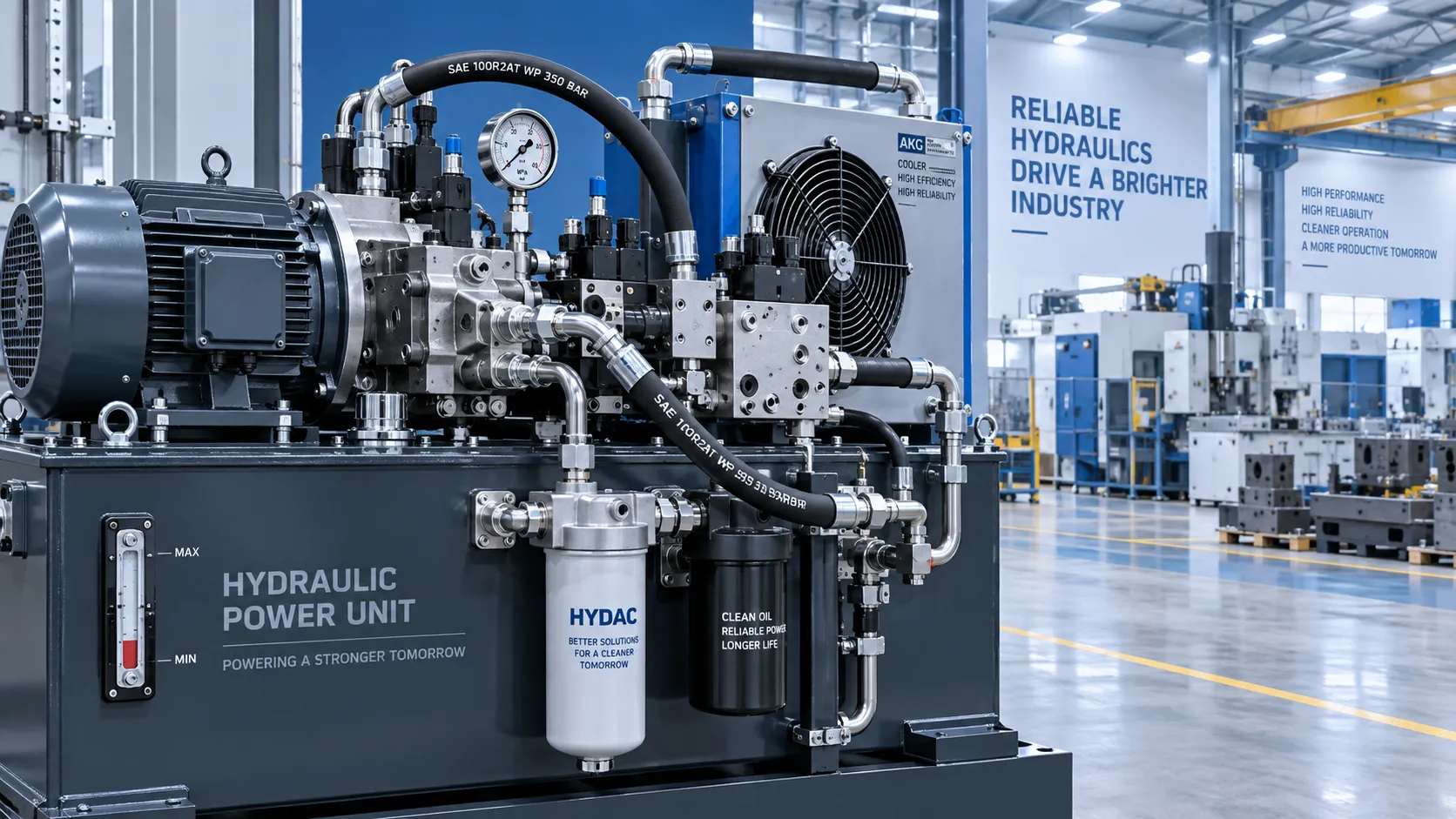
What Determines Industrial Hydraulic System Price for Heavy-Duty Equipment?
Industrial hydraulic system price depends on duty cycle, pressure, components, cooling, and integration. Compare quotes intelligently to secure reliable heavy-duty performance.
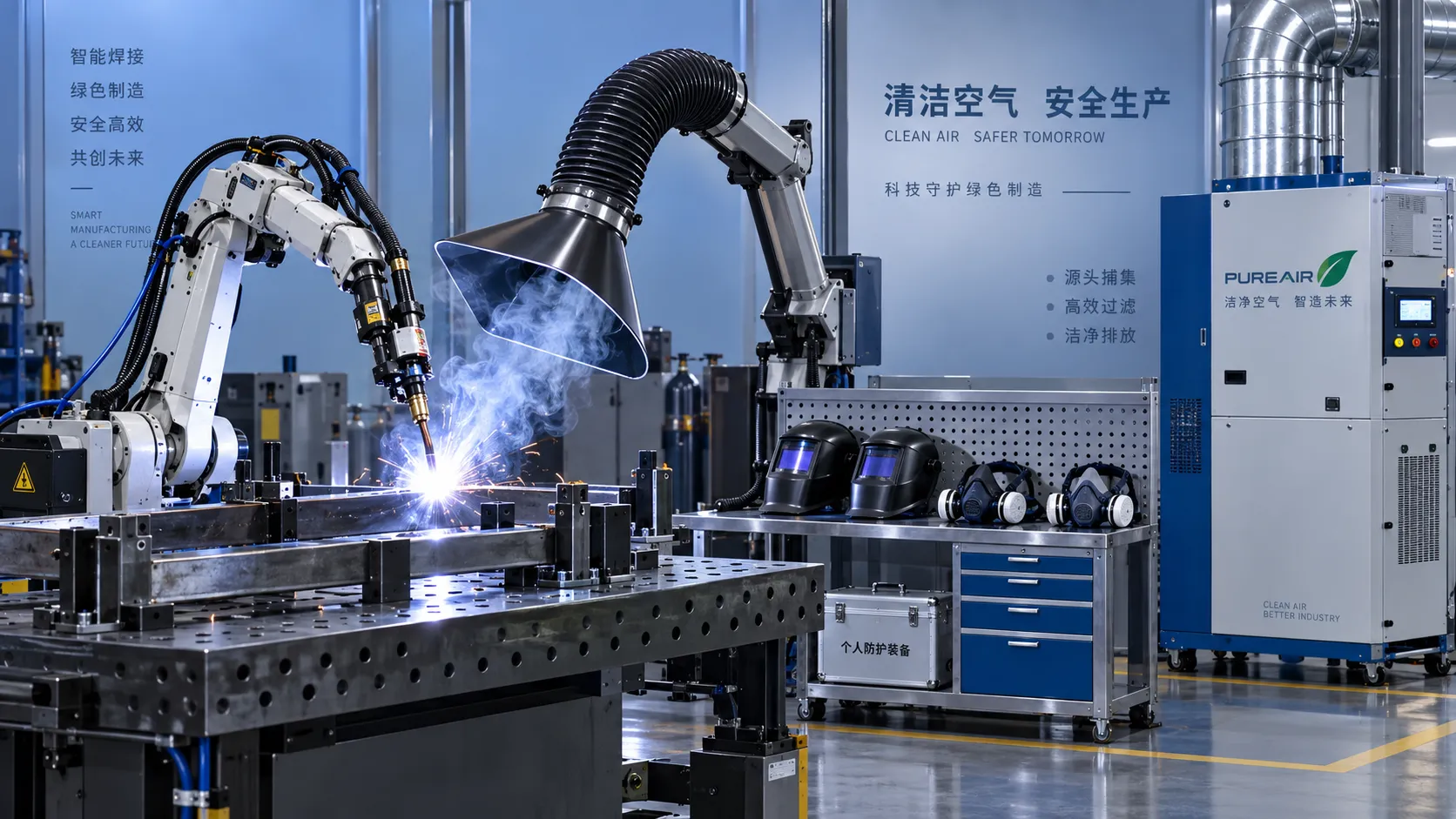
Welding Fume Extraction PPE: When Respirators Are Not Enough for Shop Safety
Welding fume extraction PPE: learn why respirators alone fall short and how source capture, ventilation, and layered controls improve shop safety.
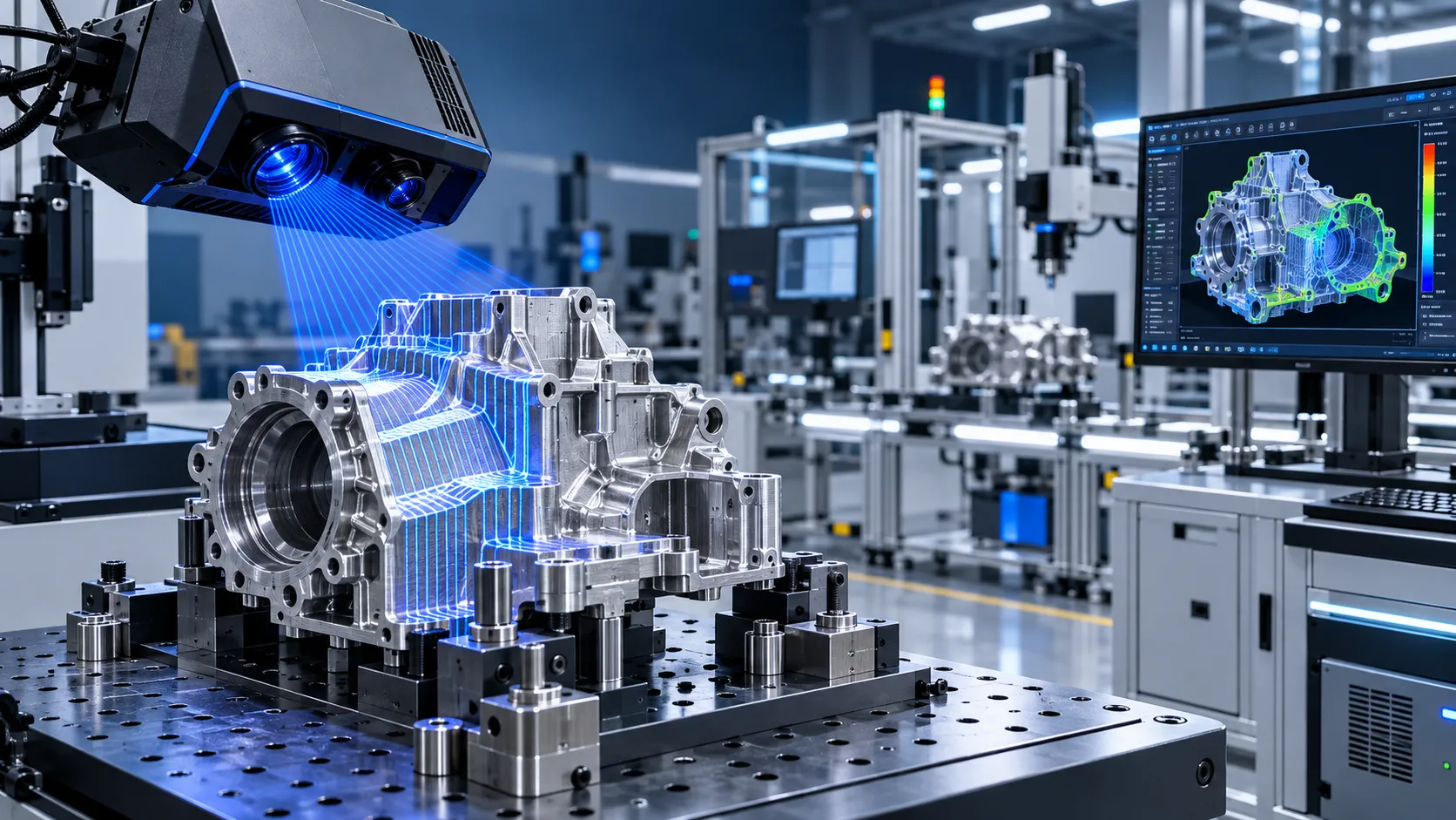
How to Select Optical Metrology Solutions for Tight-Tolerance Manufacturing
Optical industrial metrology solutions for tight-tolerance manufacturing: evaluate accuracy, surface compatibility, workflow, and traceability to select with confidence.
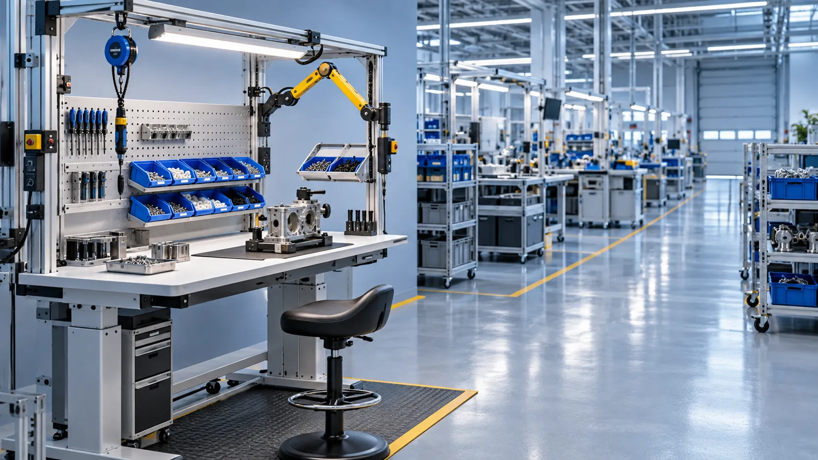
Ergonomic Standards for Assembly Workstations: A Practical Compliance Checklist
Ergonomic standards assembly checklist for safer, compliant workstations—optimize posture, reach, tools, manual handling, lighting, and repetition while supporting quality and productivity.
Related News
- 00
0000-00
Selecting Adjustable Torque Tools for Repeatable Fastener Assembly - 00
0000-00
How to Select Aerospace Inspection Tools for Aircraft Maintenance Tasks - 00
0000-00
How to Select Wire Bonding Tools for Fine-Pitch Semiconductor Packaging - 00
0000-00
Industrial Equipment Application Guidance: Match Machines to Operating Conditions - 00
0000-00
Selecting High-Speed Brushless Tool Motors for Torque, Heat, and Duty Cycle
Prof. Marcus Chen
Weekly Insights
Stay ahead with our curated technology reports delivered every Monday.