
Prototype PCB Manufacturing Equipment: What Engineers Should Evaluate Before Purchase





The right prototype PCB manufacturing equipment is not the system with the longest specification sheet. It is the system that can repeatedly produce the board features your development work needs, within a workflow your team can sustain. Before comparing models, define the work the equipment must support: proof-of-concept boards, RF layouts, fine-pitch digital assemblies, mixed-material circuits, fixture boards, or short pilot runs. Those applications place very different demands on routing accuracy, layer registration, drilling, inspection, finishing, and documentation.
For most in-house prototyping environments, the central decision is not simply “make internally or outsource.” It is whether a machine can shorten the iteration cycle without creating a new bottleneck in setup, rework, maintenance, or quality verification. Prototype PCB manufacturing equipment should be evaluated as a connected process, not as an isolated router, printer, or drill.
Start with the boards you must make, not the boards shown in a demonstration
Equipment demonstrations often use uncomplicated two-layer boards with generous tracks, large pads, and standard FR-4 laminate. Those samples can show that a machine operates, but they do not prove that it fits a real development workload. The purchase specification should be based on a representative board set drawn from current and expected projects.
Include the smallest trace-and-space combination used in normal work, the smallest drill diameters, the closest pad pitch, and the largest panel size likely to be required. Also include any board that tends to create trouble: a layout with dense connector footprints, a heat-sensitive laminate, a controlled-impedance section, an edge connector, or a design with many non-plated holes.
This approach exposes an important distinction: nominal capability is not the same as repeatable production capability. A machine may be able to produce a fine feature under ideal conditions, but reliability can fall when tool wear, board flatness, copper adhesion, dust extraction, or material variation enters the process. Purchase decisions should be based on the process window that can be maintained day after day, not on a one-time best result.
Choose the manufacturing route before choosing the machine
“Prototype PCB manufacturing” covers several different process routes. A mechanical PCB milling system subtracts copper and substrate material with routing and drilling tools. Additive or printed approaches deposit conductive material. Other systems support imaging, etching, or hybrid workflows. Each route solves a different problem, and no route is universally superior.
A mechanical system can be highly valuable when design teams need a board quickly and can work within its routing rules. It is less attractive when the regular workload depends on very dense multilayer interconnects, blind or buried vias, plated-through holes, or tightly controlled impedance structures. In those cases, internal equipment may still have a role for early-stage verification, while qualified board fabricators handle release candidates and production-intent designs.
The mistake is treating an in-house machine as a replacement for every external fabrication service. A better model is to establish a clear boundary: which designs can be made internally with confidence, which designs require outsourced fabrication from the beginning, and which designs move from one route to the other as the design matures.
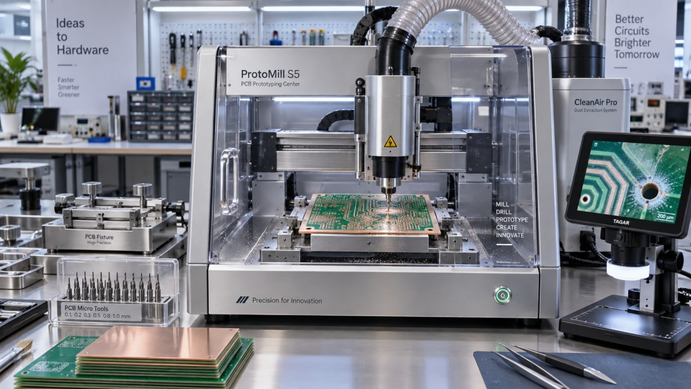
Accuracy is a system property, not a single specification
Positional accuracy matters, but it is only one part of board quality. A reliable prototype process depends on repeatability, registration, workholding, spindle or motion stability, material flatness, tool condition, and the operator’s ability to set a consistent datum. If the board must be flipped for a second side, alignment performance becomes especially important. A small error in flipping or locating the panel can make through-hole components difficult to place and can compromise annular rings around drilled holes.
Ask suppliers to explain how the equipment establishes a board origin, how it manages double-sided registration, and how it compensates for material movement or panel variation. Look for a workflow that makes setup errors visible early rather than one that assumes perfect manual placement.
Drilling should be evaluated separately from routing. Small holes are sensitive to tool runout, feed settings, backing material, substrate type, and tool replacement practices. A board can look acceptable after copper isolation yet fail during assembly because drilled holes are off-center, rough, undersized, or inconsistent. For designs using headers, connectors, and manually soldered through-hole components, drilling quality often affects usability more than marginal improvements in trace resolution.
Material compatibility changes the real cost of ownership
FR-4 is a common starting point, but it should not be the only material used to judge a system. Development programs may require aluminum-backed boards for thermal management, polyimide-based flexible materials, high-frequency laminates, thin substrates, or materials with unusual copper adhesion. Each changes cutting behavior, dust generation, heat management, fixturing needs, and tool life.
Mechanical machining of a material that produces abrasive dust can increase maintenance demands and affect motion components if extraction is weak. Thin material may need a vacuum table, carrier board, or carefully designed fixture to prevent vibration and lifting. Flexible substrates can require a process designed around their handling characteristics rather than a conventional rigid-board workflow.
Do not accept a general statement that a system “supports many materials” as sufficient evidence. The useful questions are practical: Can the material be held flat? What tooling is needed? Does the process leave burrs or delamination? How is debris removed? Can the same machine safely produce the board and maintain the expected accuracy afterward? Material compatibility should include both whether the machine can cut the material and whether the resulting process is repeatable.
Look beyond the bare board: vias, finishing, and assembly readiness
The most consequential limitation of many internal prototype workflows is not copper patterning. It is interconnection between layers. A double-sided board without plated-through holes can still be useful, but the design and assembly process must accommodate that limitation. Vias may need wire links, rivets, conductive alternatives, or soldering from both sides. These methods can be acceptable for a small functional prototype and unsuitable for dense layouts or repeated builds.
That does not make the equipment inadequate. It means the equipment must be matched to design rules and intended outcomes. If designers assume production-style plated vias while the internal process cannot provide them, iteration speed can disappear into manual rework. Establish design-rule files that reflect the actual manufacturing route, including isolation widths, pad sizes, hole constraints, copper clearances, and allowed layer transitions.
Surface condition matters as well. Freshly machined or processed copper must remain solderable through the intended assembly window. Consider how boards are cleaned, protected, stored, and prepared for solder paste or hand soldering. A fast board-fabrication step has limited value if assemblies require excessive pad cleaning, rework, or inspection before components can be placed.
Software integration determines whether speed survives contact with daily work
Prototype equipment is often purchased for turnaround time, yet file preparation can consume more time than fabrication if the software chain is poorly integrated. Review the path from ECAD output to machine execution: supported manufacturing files, layer mapping, toolpath generation, drill interpretation, panel setup, fiducial use, and revision control.
The process should preserve a clear connection between the released layout revision and the board that was made. Manual file conversion is not automatically unacceptable, but every manual translation creates an opportunity to select the wrong layer, mirror a bottom copper pattern, apply an outdated drill file, or use an obsolete design revision.
Evaluate the software with actual design data rather than a generic sample. Confirm that common elements in your library, such as polygons, slots, cutouts, vias, board outlines, and silkscreen references, translate correctly. Check whether toolpath previews make isolation areas, drill locations, and panel orientation easy to verify. A preview that exposes mistakes before material is loaded is more valuable than a workflow that relies on operator memory.
Automation has value when it removes recurring variability
Automation should be judged by the work it removes, not by how advanced it appears. Automatic tool changing, camera-assisted alignment, height sensing, vacuum workholding, barcode tracking, and integrated inspection can be valuable when they reduce common sources of variation. They may offer little benefit in a low-volume environment with a narrow, stable board range and a skilled operator who performs the same setup repeatedly.
For a shared laboratory or development center, automation can have a larger effect because it makes the process less dependent on one experienced person. The objective is not to eliminate human involvement; it is to make setup, verification, and routine recovery predictable when several people use the equipment.
Be cautious with systems whose automation creates a difficult service burden. More sensors, feeders, calibration routines, or proprietary accessories can improve throughput only if the organization has the support structure to keep them functioning. A simpler machine with documented setup procedures may deliver more usable capacity than a complex platform that waits for specialist intervention.
Maintenance, safety, and facilities belong in the purchase decision
A prototype PCB machine should be evaluated with the same discipline applied to any precision manufacturing asset. Identify consumables, expected tool changes, cleaning tasks, calibration checks, filtration needs, waste handling, noise, enclosure requirements, and extraction connections. These are not secondary operational details. They directly influence uptime, board quality, and who can realistically operate the system.
For mechanical processes, dust and chip management deserve close attention. Copper and reinforced laminate debris should be captured effectively rather than allowed to settle on motion systems, nearby electronics, or work surfaces. For chemical or curing processes, the workspace must support the relevant ventilation, handling, and cleanup practices. Equipment placement should also account for access around the machine, material staging, and the inspection bench needed to verify boards before assembly.
Serviceability is often clearer when evaluated through specific questions: Which tasks can the user perform? Which faults require a service visit? Are wear items straightforward to replace? Does the supplier provide useful troubleshooting guidance? What happens when software, control hardware, or a critical accessory is unavailable? The practical answer affects risk more than a broad service promise.
Plan quality verification before approving the capital request
Making a board is not the same as proving it is fit for use. A suitable process includes visual inspection, dimensional checks where needed, continuity testing, and a way to identify recurring defects. Depending on the boards being developed, this may include checking isolation gaps, drilled-hole alignment, edge quality, short circuits, open circuits, and board flatness.
Inspection does not need to become a production-grade quality department. It does need to match the failure modes of the chosen process. A basic microscope or magnified inspection method, repeatable electrical checks, and clear acceptance criteria can prevent unreliable prototypes from being mistaken for design failures. That distinction is important: when a test board fails, the team needs to know whether the circuit design is wrong or the board fabrication introduced the fault.
A practical purchase evaluation sequence
- Define the internal-use boundary. State which board types the equipment must produce and which will remain externally fabricated.
- Build a representative test package. Include ordinary boards and the layouts that challenge your present workflow.
- Assess the complete process. Review design export, setup, fabrication, cleaning, inspection, and assembly preparation rather than only machine cycle time.
- Test repeatability. Request or conduct repeated runs, including double-sided alignment and small-hole drilling where relevant.
- Model operating burden. Include tooling, consumables, maintenance time, operator training, workspace needs, and quality checks.
- Document design rules. Confirm that the chosen equipment’s limits can be translated into usable ECAD constraints before it enters routine use.
When a lower-capability system is the better decision
A modest system can be the sounder purchase when its limits match a disciplined prototype strategy. For example, a team making adapter boards, test fixtures, sensor interfaces, low-density control boards, and mechanical-electrical mockups may gain more from quick setup and reliable routing than from a costly platform aimed at board types it rarely needs.
A more capable system becomes justified when its additional functions solve a recurring constraint: frequent double-sided registration problems, repeated small-feature work, a need for greater material range, high setup variation among users, or a workflow where manual steps are delaying engineering decisions. The justification should come from the bottleneck it removes, not from the possibility that the feature may be useful someday.
Prototype PCB manufacturing equipment earns its place when it creates dependable learning cycles: a layout is released, a board is produced, its quality is understood, and the next design decision can be made without avoidable delay. Evaluate every machine against that cycle. The best fit is the one that turns internal fabrication into a controlled engineering capability rather than a fast but unpredictable experiment.
Related News
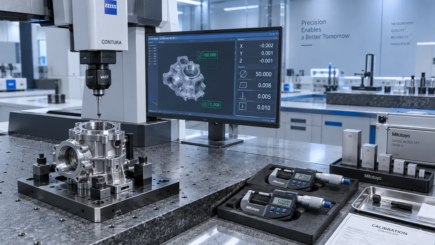
How to Select High-Precision Measuring Instruments for Tight-Tolerance Production?
High-precision measuring instruments are essential for tight-tolerance production. Learn how to evaluate accuracy, repeatability, environment, calibration, and data integration.
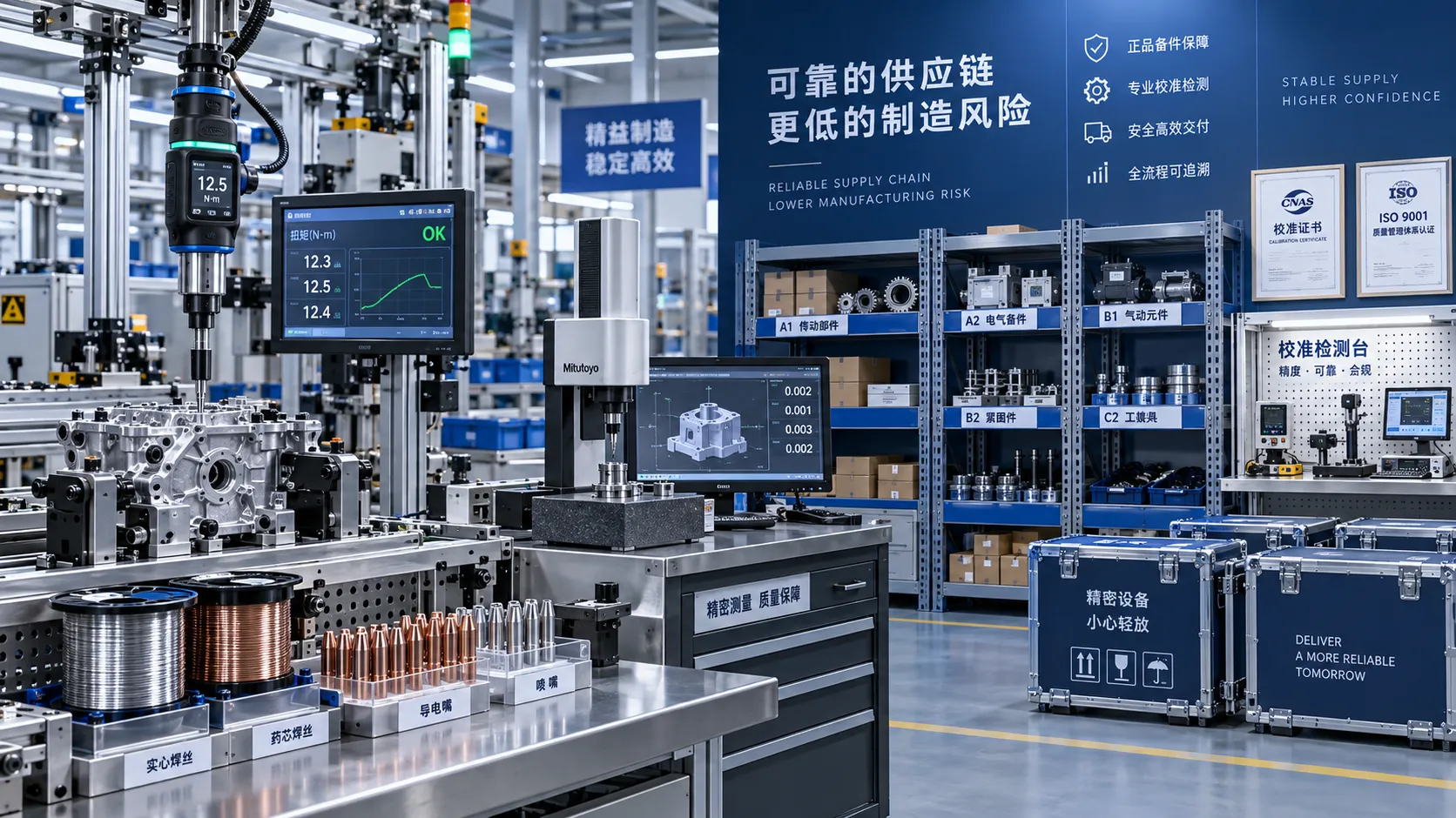
How Industrial Innovation Supplier Networks Reduce Sourcing Risk for Manufacturers
industrial innovation supplier network insights help manufacturers reduce sourcing risk, control lifecycle costs, and choose reliable tools, services, and suppliers with confidence.
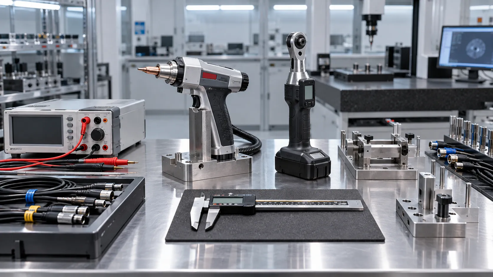
Which Industrial Standards Should Be Checked Before Export?
Which industrial standards should be checked before export? Discover essential compliance steps for industrial tools, welding equipment, laser systems, and metrology products.
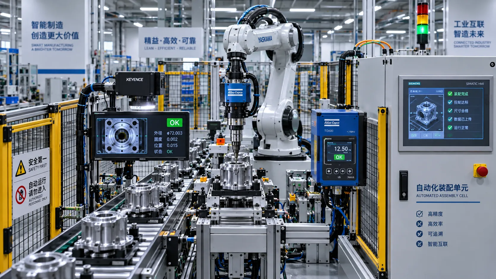
What Industrial Automation Exporters Need to Know Before Entering ASEAN Markets
Industrial automation exporter to ASEAN: learn how to navigate compliance, local service, digital readiness, pricing, and market entry for scalable growth.
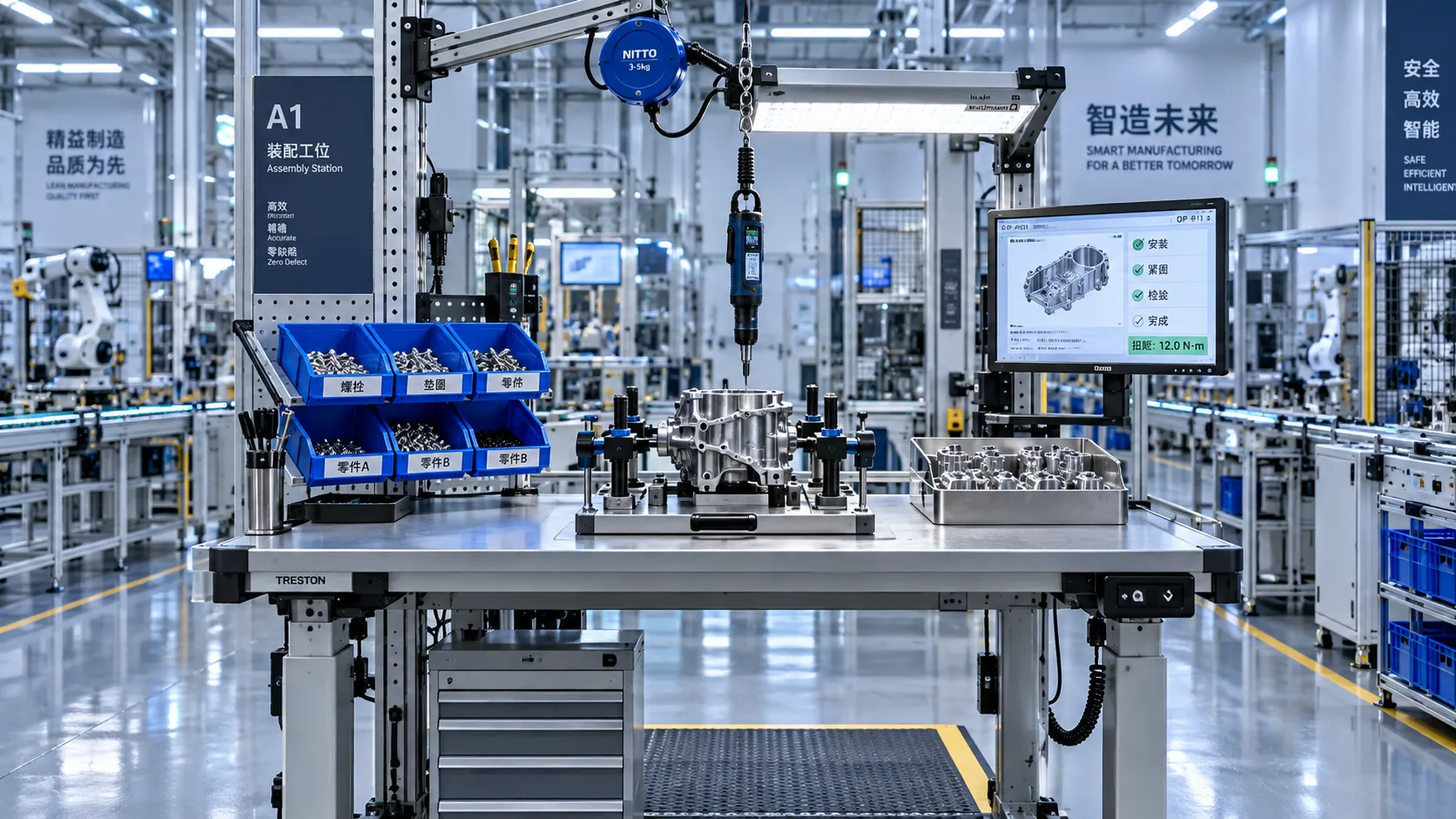
Workplace Ergonomics for Manufacturing: Reducing Repetitive-Strain Risks on Assembly Lines
Workplace ergonomics for manufacturing helps reduce repetitive-strain risks on assembly lines through smarter workstation design, tool selection, task analysis, and quality-focused improvements.
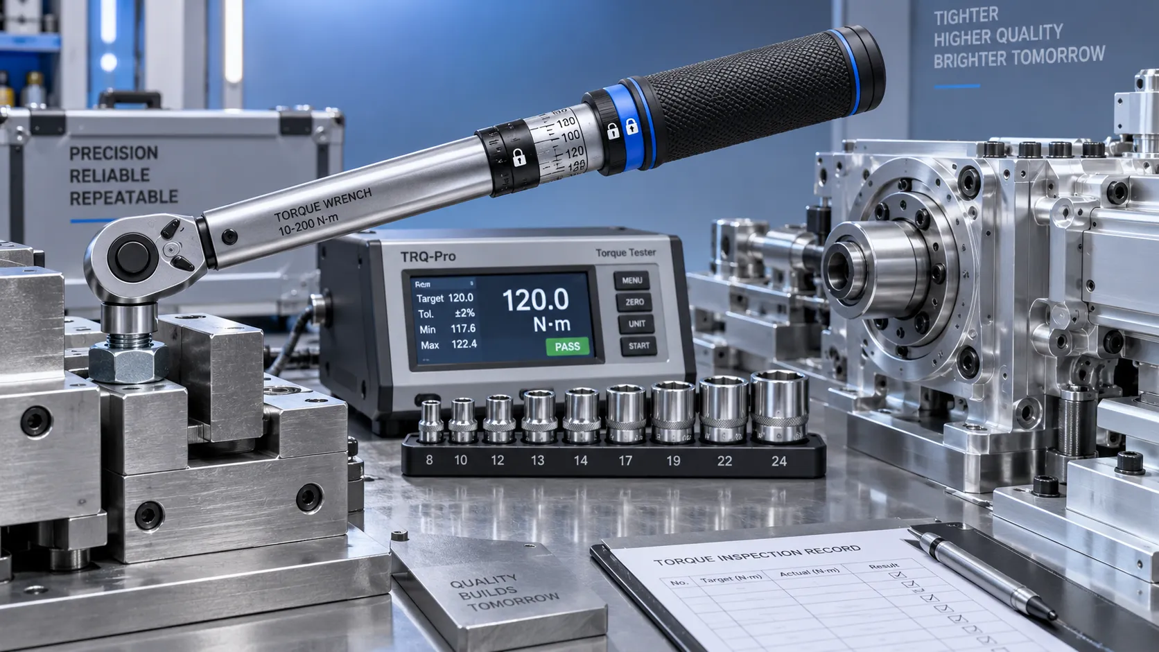
Selecting Adjustable Torque Tools for Repeatable Fastener Assembly
Adjustable torque tools: learn how to match range, accuracy, control methods, calibration, and ergonomics for repeatable, reliable fastener assembly.

How to Select Aerospace Inspection Tools for Aircraft Maintenance Tasks
Aerospace maintenance inspection tools: learn how to select reliable, traceable equipment for aircraft access, accuracy, calibration, and compliant maintenance decisions.
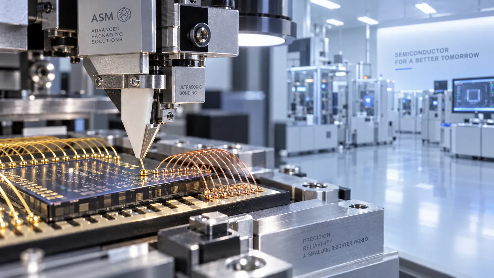
How to Select Wire Bonding Tools for Fine-Pitch Semiconductor Packaging
Explore semiconductor manufacturing tools for wire bonding and learn how to select precision solutions for fine-pitch packaging, reliable loops, accuracy, and yield.
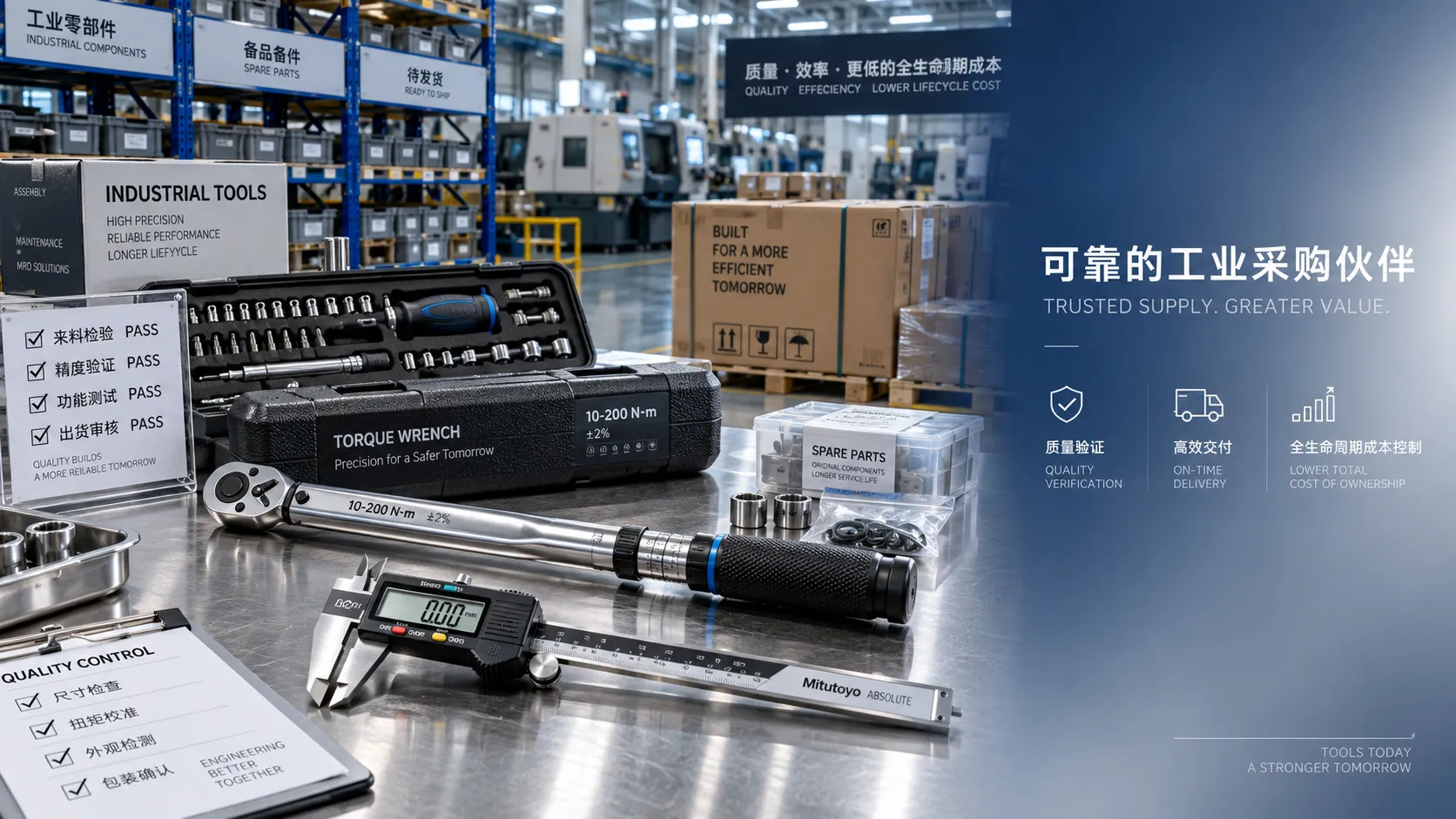
How to Compare Industrial Tool Suppliers for Quality, Lead Time, and Total Cost
Industrial tool selection supplier comparison made simple: evaluate quality, lead times, total cost, service, and supply resilience for confident sourcing decisions.
Related News
- 00
0000-00
How to Select High-Precision Measuring Instruments for Tight-Tolerance Production? - 00
0000-00
Prototype PCB Manufacturing Equipment: What Engineers Should Evaluate Before Purchase - 00
0000-00
Workplace Ergonomics for Manufacturing: Reducing Repetitive-Strain Risks on Assembly Lines - 00
0000-00
Selecting Adjustable Torque Tools for Repeatable Fastener Assembly - 00
0000-00
How to Select Aerospace Inspection Tools for Aircraft Maintenance Tasks
Prof. Marcus Chen
Weekly Insights
Stay ahead with our curated technology reports delivered every Monday.