
Electronics Prototyping Tools for Faster Design Validation and Small-Batch Testing





A fast prototype is not necessarily a useful prototype. The meaningful milestone is a unit that has been measured under realistic electrical, mechanical, and assembly conditions, with enough evidence to explain what will happen when the design is repeated in a small batch. Electronics prototyping tools matter because they shorten the distance between a suspected fault and a defensible answer.
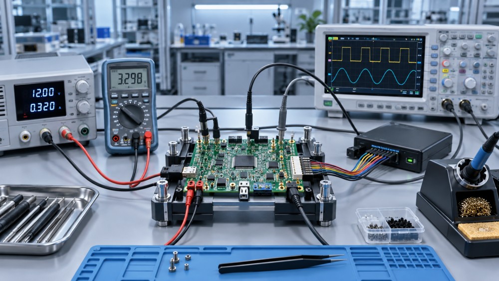
For operators assembling and testing early electronic products, the most effective setup is rarely the largest collection of instruments. It is a connected tool chain: safe power delivery, controlled assembly, measurement at the right test points, repeatable programming, and a simple way to record failures. A breadboard, soldering station, digital multimeter, bench power supply, oscilloscope, logic analyzer, PCB holder, and basic test fixture can cover a large share of design-validation work when each tool is used for the decision it can actually support.
Validation starts by separating concept proof from production evidence
A breadboard is excellent for answering whether a circuit concept works: whether a sensor is readable, a regulator can supply a load, or a microcontroller can communicate with a peripheral. It is much less reliable for proving signal integrity, thermal behavior, current capacity, or mechanical durability. Long jumper wires add resistance, inductance, and accidental antenna effects. Loose contacts can create intermittent failures that resemble firmware or component problems.
That distinction becomes critical when moving from a bench prototype to a first PCB revision. A circuit that performs correctly on a breadboard can fail after layout because the physical implementation has changed: return paths are different, switching currents are concentrated, connector pinouts can be reversed, and a component package may dissipate heat differently from its through-hole equivalent.
Early validation is more efficient when each prototype answers a defined question:
- Concept prototype: Does the functional block operate at all?
- Engineering prototype: Does the schematic and PCB implementation meet electrical requirements?
- Assembly prototype: Can the board be soldered, programmed, inspected, and reworked consistently?
- Small-batch test unit: Can the same pass/fail checks be applied repeatedly across multiple boards?
Using the same improvised test method at every stage creates confusion. A temporary jumper-wire setup may be adequate for a concept check, while a small batch needs fixed connector orientation, controlled supply limits, documented test points, and a repeatable sequence.
Build the bench around fault isolation, not around instrument count
The most useful electronics prototyping tools are those that help isolate a fault without introducing another one. A basic bench should make it easy to answer four questions: Is the correct voltage present? Is the circuit drawing the expected current? Is the signal changing as intended? Is the board assembled as designed?
A current-limited bench power supply is often the first instrument used on a newly assembled board. It should not be treated merely as a voltage source. Setting a conservative current limit before first power-up can prevent damaged traces, overheated ICs, and destroyed prototypes when a solder bridge or polarity error is present. The current display also provides an immediate diagnostic clue. A board that reaches its current limit at power-on may have a shorted rail, reversed polarized component, incorrect IC orientation, or a load that starts earlier than expected.
A digital multimeter remains the fastest tool for continuity checks, resistance-to-ground checks, DC rail verification, diode-mode inspection, and basic current measurement. However, it cannot show short-duration voltage dips, switching ripple, startup sequencing, or communication timing. Those problems require an oscilloscope or logic analyzer.
The oscilloscope becomes essential when a circuit appears correct in static measurements but behaves unpredictably. It can reveal regulator instability, reset pulses, PWM duty-cycle errors, ringing at switching nodes, and noise on an analog reference. Probe technique matters as much as instrument bandwidth. A long ground lead can pick up noise and exaggerate ringing. For fast edges or switching converters, use the shortest practical ground connection, keep the probe near the measured node, and confirm that the probe attenuation setting matches the oscilloscope channel setting.
Logic analyzers serve a different purpose. They are efficient for checking whether digital buses such as UART, I²C, SPI, or GPIO lines are active and correctly timed at a protocol level. They do not replace an oscilloscope when voltage margins, edge shape, overshoot, or analog noise are in doubt. A decoder may display valid-looking bytes even when the electrical waveform has poor margins that become a field failure later.
Power-up discipline prevents avoidable prototype losses
First power-up should be a controlled inspection step rather than a moment of discovery. Before applying power, compare the assembled board with the bill of materials, placement drawing, and polarity markings. Verify that high-risk components are correct: regulators, diode orientation, electrolytic and tantalum capacitors, MOSFETs, IC pin-1 orientation, connectors, and any components with similar packages but different values.
Resistance checks between each power rail and ground are useful, but they need interpretation. A low measured resistance does not always mean a short circuit; some circuits contain low-resistance loads, large capacitor banks, or semiconductor paths that affect the reading. The value is most useful when compared with the expected circuit structure or with a known-good board. Diode-mode readings can be more informative for identifying a direct junction path or a reversed component.
After the visual and unpowered checks, apply the lowest valid operating voltage with a current limit appropriate to the design. Observe current before enabling every subsystem. If the design has separate rails, bring them up in a deliberate order where practical. Check rail voltage at the load, not only at the supply terminals. Voltage can be lost across thin jumper wires, weak clips, undersized connectors, or PCB traces carrying unexpected current.
When a board exceeds its expected current draw, avoid repeatedly cycling power in the hope that the behavior changes. Remove power, inspect the thermal area, and narrow the fault. Thermal imaging equipment can be useful, but it is not mandatory for basic fault finding. A cautious touch test on unpowered hardware is not a substitute for measurement; energized boards can contain hazardous voltages or components that heat quickly. For low-voltage boards, non-contact temperature methods or a thermal camera can identify a hot component without disturbing the circuit.
Assembly quality is part of electrical validation
Many prototype faults are assembly faults, not design faults. A solder joint can look acceptable while being electrically unreliable, especially around fine-pitch leads, large thermal pads, shielded connectors, and components with hidden terminations. Good lighting, magnification, flux control, and a stable PCB holder are not cosmetic workshop additions; they affect whether defects can be found before measurements become misleading.
A temperature-controlled soldering iron with suitable tip geometry is more useful than a high-power iron operated at excessive temperature. The goal is to transfer heat into the joint efficiently, not to compensate for poor heat transfer by overheating pads and components. Small conical tips are not automatically best for fine work; a compact chisel or hoof tip often transfers heat more effectively to pads and leads. For surface-mount rework, hot air can be appropriate, but uncontrolled airflow can displace nearby passives or overheat plastic connectors.
Flux selection and cleaning also affect inspection. Residue may be benign in some applications, but it can obscure bridges, trap debris, or complicate high-impedance measurements. Where cleanliness matters, use a compatible cleaning process and allow the board to dry fully before powered testing. Electrostatic-discharge precautions are especially important for exposed CMOS inputs, RF devices, sensor front ends, and unprotected components handled before installation.
Mechanical stress deserves attention before a design reaches a small batch. Repeated connector insertion, strain on USB or power sockets, unsupported heavy components, and flexing near panel mounts can create faults absent from a stationary bench test. A simple fixture that holds the enclosure, cable, and board in their intended positions often exposes these issues earlier than extended electrical troubleshooting.
Use test points and fixtures to make a small batch comparable
Once more than a few boards are being assembled, hand-probing each net becomes slow and inconsistent. The design should provide accessible test points for power rails, ground, programming, reset, critical analog outputs, and major communication lines. Test points need enough clearance for the intended probe or pogo pin. A tiny exposed pad located between tall components may exist on the layout but remain impractical during testing.
A small-batch fixture does not need to be a complex automated bed-of-nails system. It can begin as a rigid locating plate, a connector interface, labeled probe points, and a controlled power switch. Its purpose is repeatability: every board is powered the same way, receives the same firmware image, and is checked against the same acceptance conditions.
Useful fixture functions include:
- preventing reverse connection of power and programming cables;
- holding the PCB so probes do not slip during measurement;
- providing a known load or stimulus for inputs and outputs;
- making serial-number or firmware-version recording part of the test sequence;
- isolating the unit under test from accidental movement and intermittent cable contact.
For example, a board controlling a relay or motor driver should be checked with a load that represents the expected electrical behavior, not only with an indicator LED. An LED may confirm that a logic signal exists while concealing inadequate current capability, supply droop, flyback problems, or excessive switching noise. Conversely, a full production load may be unsafe or unnecessary during an early circuit check. The test load should match the question being validated.
Make measurements traceable enough to support design decisions
Prototype work loses value when a result cannot be reproduced. A simple test record is usually sufficient: board revision, component substitutions, firmware version, supply voltage and current limit, instrument settings, measured values, observed behavior, and disposition. Photographs of the assembly before rework can be helpful when later failures need to be correlated with soldering or placement conditions.
Instrument configuration should be recorded whenever it affects interpretation. Oscilloscope bandwidth limiting, probe ratio, AC or DC coupling, trigger source, sample rate, and time base can all change what is visible. For current readings, note whether the value came from the bench supply, a multimeter in series, or a current probe; these methods have different resolution and can affect the circuit differently.
It is equally important to distinguish a failed board from a failed test setup. A loose ground clip, discharged battery, damaged cable, incorrect fixture wiring, or outdated firmware can produce symptoms that look like a hardware defect. Keeping one known-good reference unit is a practical way to verify the test method before rejecting a group of newly assembled boards.
Tool selection should follow the failure mode being investigated
Buying more capable equipment does not automatically improve validation. A high-bandwidth oscilloscope will not solve a missing test point; an automated fixture cannot compensate for an unclear acceptance criterion; an expensive soldering station cannot correct a footprint with insufficient pad spacing. The best purchase is the tool that removes the current bottleneck in diagnosis or repeatability.
For low-voltage digital products, a stable current-limited supply, dependable multimeter, temperature-controlled soldering equipment, magnification, and a modest oscilloscope commonly provide more practical value than specialized instruments acquired before their need is established. As designs add switching power, sensitive analog sections, higher-speed interfaces, RF functions, or safety-critical power stages, the measurement method must become more rigorous. That may require differential probing, isolated measurement practices, electronic loads, spectrum analysis, environmental testing, or formal compliance evaluation beyond the prototype bench.
Electronics prototyping tools deliver their greatest value when they turn troubleshooting into a controlled comparison: expected versus measured voltage, intended versus observed waveform, approved versus assembled component, known-good versus suspect unit. That discipline reduces wasted rework, reveals whether a fault belongs to the design or the assembly process, and produces the evidence needed before a small batch is treated as ready for wider production.
Related News

Choosing an Industrial IoT Platform: Key Criteria for Legacy Equipment
Choose an industrial IoT platform for legacy equipment with confidence. Discover key checks for connectivity, data integrity, security, and lifecycle costs before investing.

In-House vs. Outsourced Aircraft Maintenance: Comparing Total Costs
Compare aerospace maintenance cost for in-house vs. outsourced aircraft upkeep. Discover hidden expenses, downtime impacts, and break-even factors to find the best fit for your fleet.
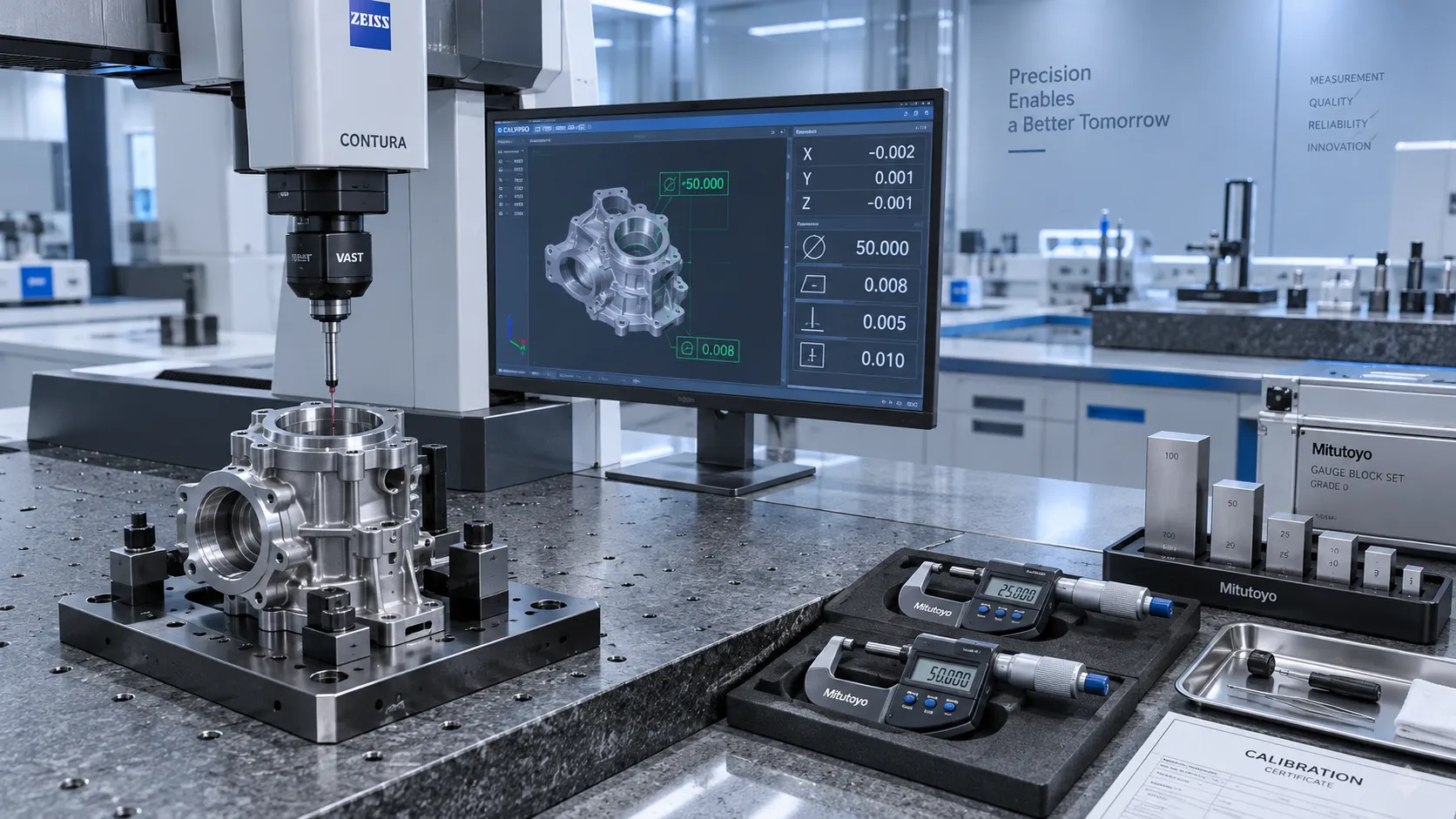
How to Select High-Precision Measuring Instruments for Tight-Tolerance Production?
High-precision measuring instruments are essential for tight-tolerance production. Learn how to evaluate accuracy, repeatability, environment, calibration, and data integration.

How Industrial Innovation Supplier Networks Reduce Sourcing Risk for Manufacturers
industrial innovation supplier network insights help manufacturers reduce sourcing risk, control lifecycle costs, and choose reliable tools, services, and suppliers with confidence.

How Do Advanced Manufacturing Methods Improve Batch Consistency?
How do advanced manufacturing methods improve batch consistency? Discover how precision metrology, intelligent torque control, welding automation, and traceable data reduce variation and improve quality.

South East Asia Machine Tools Market: Demand Outlook by Manufacturing Industry
South East Asia machine tools market outlook: explore demand from automotive, electronics, fabrication, and infrastructure, plus smart sourcing priorities for manufacturers.
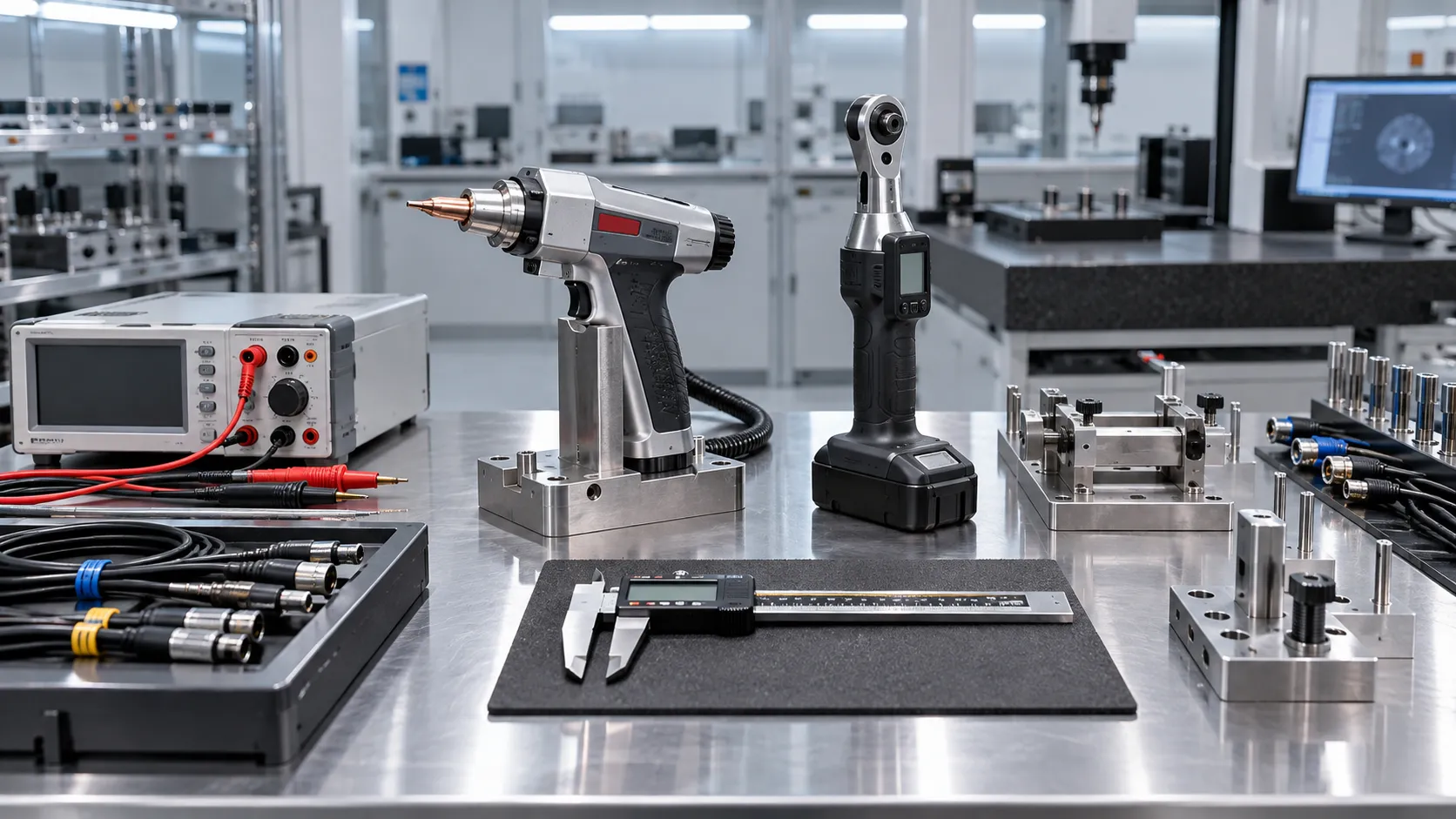
Which Industrial Standards Should Be Checked Before Export?
Which industrial standards should be checked before export? Discover essential compliance steps for industrial tools, welding equipment, laser systems, and metrology products.

What Industrial Automation Exporters Need to Know Before Entering ASEAN Markets
Industrial automation exporter to ASEAN: learn how to navigate compliance, local service, digital readiness, pricing, and market entry for scalable growth.
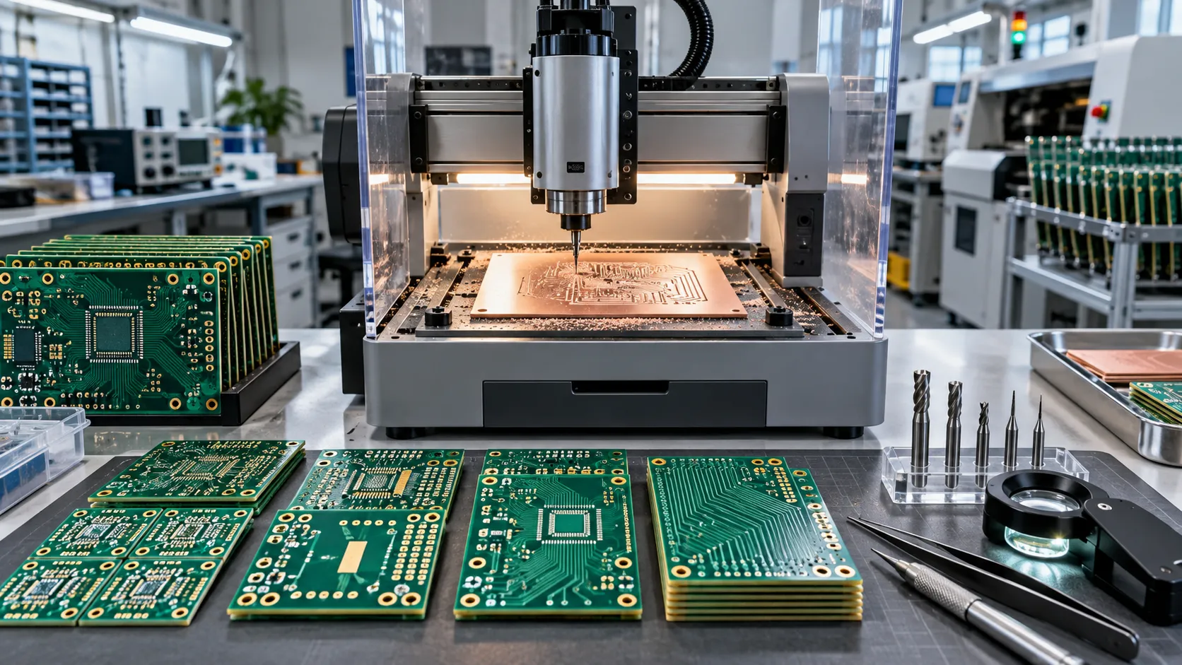
PCB Prototyping Equipment Costs: Comparing In-House Machines and Outsourced Builds
PCB prototyping equipment costs compared: discover when in-house machines speed iterations and when outsourced builds deliver better value, quality, and scalability.
Related News
- 00
0000-00
Choosing an Industrial IoT Platform: Key Criteria for Legacy Equipment - 00
0000-00
How to Select High-Precision Measuring Instruments for Tight-Tolerance Production? - 00
0000-00
How Do Advanced Manufacturing Methods Improve Batch Consistency? - 00
0000-00
Electronics Prototyping Tools for Faster Design Validation and Small-Batch Testing - 00
0000-00
Prototype PCB Manufacturing Equipment: What Engineers Should Evaluate Before Purchase
Prof. Marcus Chen
Weekly Insights
Stay ahead with our curated technology reports delivered every Monday.