
How to Prototype Electronic and Semiconductor Parts for Early Performance Testing





Prototype for the Failure Mode You Need to Expose
Early performance testing is useful only when the prototype preserves the conditions that drive product behavior. A board that powers up on a bench can still be a poor prototype for evaluating a switching regulator, RF front end, optical sensor, high-current connector, or power semiconductor. If its layout, thermal path, package attachment, interconnect geometry, or assembly process differs too far from the intended build, the test may produce a reassuring result with little decision value.
For technical evaluators, electronics and semiconductors parts prototyping is therefore less about making the first functional article quickly and more about deciding which production realities must be represented at each stage. The right prototype is rarely a full imitation of volume production. It is a controlled approximation that makes the most consequential electrical, thermal, mechanical, and manufacturing assumptions visible early enough to change the design.
The practical question is: what must this prototype prove, and which deviations from the final part would invalidate that proof?
Start With the Decision, Not the Prototype Format
Prototype programs often begin with a familiar choice: development board, breadboard, machined housing, quick-turn PCB, or a limited pilot build. That sequence can lead to unnecessary cost or, worse, a test article that answers the wrong question. The better starting point is the engineering decision that will follow the test.
If the decision concerns basic circuit operation, a modular evaluation board may be sufficient. It can establish whether a controller starts correctly, whether a sensor output is readable, or whether a power stage follows its intended control logic. But when the decision concerns switching loss, signal integrity, junction temperature, electromagnetic emissions, contact resistance, mechanical shock, or manufacturability, a more representative assembly is usually required.
Before releasing any prototype package, write down three items:
- The measurable claim being tested, such as efficiency at a defined load, stable communication at a defined data rate, or thermal margin in an enclosed assembly.
- The operating conditions that make the claim meaningful, including supply voltage, load profile, ambient temperature, airflow, mounting orientation, cable configuration, and duty cycle.
- The design variables that the test must preserve, such as copper weight, layer stack-up, package land pattern, heat sink interface, solder process, connector retention, or enclosure material.
This discipline prevents a common error: using a low-fidelity functional prototype to make a high-confidence reliability or production decision. A prototype does not become representative because it contains the same bill of materials. Geometry, interfaces, assembly variation, and operating boundary conditions often matter as much as component selection.
Match Prototype Fidelity to the Dominant Physics
Electronic assemblies fail for different reasons, and prototype fidelity should follow the dominant failure mechanism. An embedded controller board and a high-density power module may use similar fabrication methods, yet demand very different early testing priorities.
Electrical behavior: preserve parasitics when they matter
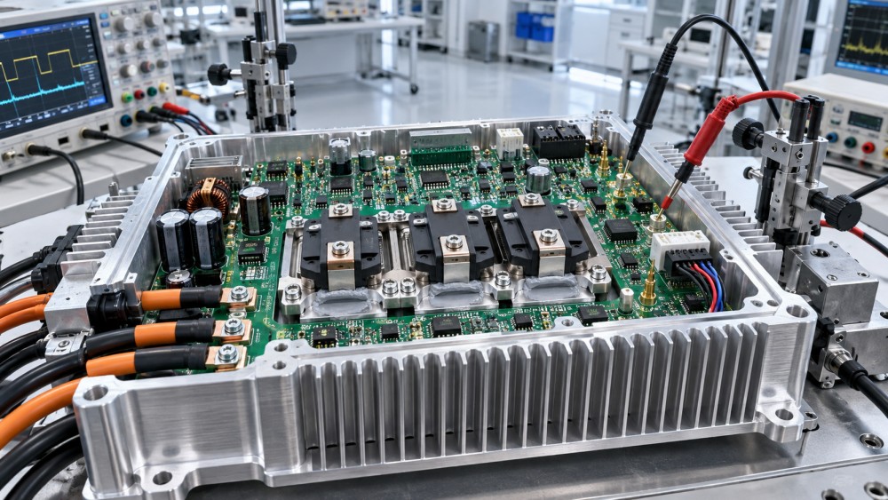
At low frequencies and modest current levels, a prototype can tolerate a degree of wiring flexibility. At high switching speeds, fast edge rates, low-voltage logic margins, or sensitive analog measurements, parasitic inductance, capacitance, impedance discontinuities, and return-path geometry become part of the circuit. Flying leads, oversized adapter boards, long probe grounds, and altered connector placement can create ringing or noise that is absent from the intended design, or mask a problem that will appear later.
For these cases, the prototype should use the target PCB stack-up where practical, a realistic component placement pattern, and controlled return paths. Test points are still necessary, but they should be designed so that measurement access does not materially change the circuit under test. A waveform captured with an unsuitable probe arrangement can be more misleading than no waveform at all.
Thermal behavior: model the full heat path
Semiconductor temperature is governed by the complete route from die to ambient: package, solder joints or attach layer, thermal vias, copper planes, dielectric materials, interface materials, heat spreaders, chassis contact, airflow, and enclosure boundaries. A component mounted on an open development board may appear comfortably cool, while the same component in a compact product enclosure operates close to its temperature limit.
Thermal prototypes should reproduce the meaningful portions of that path. If the production design relies on a metal housing as a heat sink, testing without it is incomplete. If pad voiding, mounting pressure, flatness, or thermal interface material selection can influence heat transfer, those variables should be controlled and recorded. Surface temperature alone is not always enough; evaluators need a defensible link between external measurements and the semiconductor condition that affects lifetime and operating margin.
Mechanical behavior: include the interfaces, not only the enclosure
Mechanical testing often starts too late because it is treated as a packaging task. In practice, connectors, solder joints, heavy components, threaded fasteners, cable strain relief, PCB support points, and tolerance stack-up can all affect electrical performance and service life. A prototype intended for vibration, insertion-cycle, drop, or torque evaluation should include production-relevant attachment methods and mass distribution.
For assemblies with large inductors, relays, power modules, or cable-mounted connectors, the board support scheme is especially important. A mechanically simplified test article may conceal flexing that later causes intermittent connections, cracked joints, or damage around mounting holes.
Choose the Prototype Path Deliberately
No single build method works across all early tests. The useful distinction is not between “prototype” and “production,” but between the confidence required from the test and the cost of representing final conditions.
The transition between these stages should be driven by uncertainty, not by a calendar milestone. A design may need a process-representative build early if its performance depends on fine-pitch packages, large thermal pads, unusual substrates, high-current joints, or tight mechanical alignment. Conversely, an architecture still undergoing major circuit changes may benefit more from rapid electrical iterations before a higher-fidelity build is justified.
For semiconductor parts, package availability also affects the path. A device may be available only in a package that is difficult to rework or inspect, or early samples may differ from the intended production package. Treat package equivalence as a test assumption requiring explicit review. Pin compatibility does not ensure equivalent thermal resistance, switching behavior, package stress, or assembly response.
Build a Test Vehicle That Can Diagnose, Not Just Detect
A prototype that fails without revealing why creates another design cycle with little learning. Diagnostic features should be planned into the article from the beginning, particularly when parts will be difficult to access after enclosure assembly or environmental testing.
Useful provisions include measurement pads at relevant power and signal nodes, current-sense locations, temperature-sensor attachment points, selectable component footprints, controlled test jumpers, and documented fixture interfaces. These features must be placed with restraint. Large stubs on fast signals, added resistance in high-current paths, or poorly located test points can alter the result. The objective is to create observability without changing the behavior under investigation.
For thermal characterization, record enough information to repeat the setup: ambient conditions, airflow arrangement, input power, load state, stabilization time, enclosure configuration, mounting torque where applicable, and measurement location. For electrical testing, preserve the supply source, cable length, probe method, instrument bandwidth settings, termination conditions, and load characteristics. Without this context, a result may not be comparable between prototype revisions.
Inspection should also begin early. Visual inspection alone may not reveal solder voids beneath exposed pads, insufficient wetting in hidden joints, warped assemblies, or damage introduced by rework. The appropriate inspection method depends on package and construction, but the principle remains constant: inspect the interfaces that carry the performance risk. A thermal anomaly or intermittent electrical result may originate in assembly quality rather than in the circuit design.
Separate Component Qualification From Design Validation
A frequent source of confusion is treating a component data sheet, supplier qualification status, or prior use in another product as proof that the component is suitable in a new assembly. Those sources are valuable, but they answer different questions.
Component-level information can establish rated conditions, recommended land patterns, package handling requirements, and device-specific performance boundaries. Design validation determines whether the component behaves acceptably in the actual circuit, layout, thermal environment, mechanical assembly, and usage profile. The distinction is particularly important for power semiconductors, high-frequency devices, sensors, connectors, and components exposed to repeated mechanical loading.
Technical evaluators should ask whether a failure has been assigned to the right level of the system. An excessive temperature rise may stem from a device selection issue, but it may also result from insufficient copper area, an unsuitable thermal interface, airflow restriction, or a control-loop condition that raises dissipation. A communications fault may point to the transceiver, but could originate in grounding, cable termination, common-mode noise, or fixture behavior. Early prototypes are valuable because they allow these interactions to be tested before changes become expensive.
Use Standards as Test Structure, Not a Substitute for Engineering Conditions
Recognized industry standards and supplier recommendations can provide a useful starting structure for handling, assembly, inspection, environmental exposure, and reliability-oriented testing. They help teams define repeatable terminology and avoid overlooking established controls. They do not automatically define the operating profile of a particular product.
A test program should translate intended use into conditions that can be measured and repeated. For example, “high temperature,” “frequent cycling,” or “harsh handling” are too vague to support a design decision. The evaluation needs a temperature range, dwell or transition logic where relevant, electrical loading state, mechanical constraint, and pass/fail criteria. The same principle applies to electrical overstress, moisture exposure, vibration, and connector mating cycles.
Pass/fail criteria deserve early attention. A prototype may remain functional while already showing drift, elevated resistance, changing waveform margin, increased leakage, reduced thermal headroom, or mechanical damage. For early performance testing, these shifts can be more informative than a binary failure. They indicate where the design margin is being consumed and whether the next prototype should change a component, a layout feature, an assembly process, or an operating limit.
Common Prototype Shortcuts That Distort Results
Several shortcuts are reasonable for exploration but unsafe when used to support a release decision. Hand-soldered samples can be appropriate for functional work, yet may not represent production solder quality for bottom-terminated packages, thermal pads, or densely populated boards. Bench supplies and resistive loads are useful, but may fail to reproduce transients from motors, batteries, switching loads, or long cables. An open-frame test can simplify debugging, while concealing enclosure-driven heating and electromagnetic coupling.
Rework is another area that needs discipline. It may be necessary during iteration, but repeated heating, pad repair, altered interface material, or substitution of a mechanically similar component can change the behavior under test. Each deviation does not invalidate the prototype, but it should be documented so results are not mistakenly attributed to the nominal design.
The most defensible early test report does not claim that a prototype proves everything. It states what configuration was tested, what conditions were represented, which production features were intentionally excluded, and what decision the evidence supports. That level of clarity helps engineering, manufacturing, quality, and sourcing teams distinguish a promising result from a release-ready conclusion.
Move Forward When the Remaining Uncertainty Is Explicit
Prototyping should progressively remove the uncertainties that could change the product decision. A first article may establish electrical feasibility. A later build may show whether the thermal and mechanical design preserves that performance. A process-representative build may then test whether the result survives normal assembly variation and inspection requirements.
The goal is not to make every early sample look like a finished product. It is to make each prototype answer a specific question with enough fidelity that the next investment is justified. When electrical behavior, heat flow, interconnect quality, and real operating conditions are represented in proportion to their risk, early performance testing becomes a decision tool rather than a demonstration exercise.
Related News

Equipment Application Guidance for the Middle East: Managing Heat and Dust
Explore application guidance Middle East teams can use to manage heat and dust, protect welding equipment, batteries and precision tools, and reduce downtime. Get practical tips.
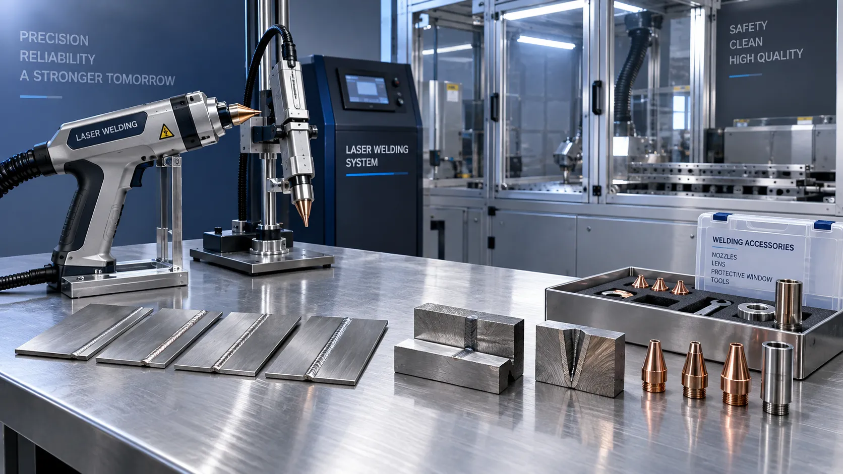
Choosing a Handheld Laser Welding Supplier: Weld Trials, Training, and Service
Choose a handheld laser welding supplier with proven weld trials, safety training, and reliable service. Learn what to verify before buying to reduce downtime and protect your investment.

Choosing an Industrial IoT Platform: Key Criteria for Legacy Equipment
Choose an industrial IoT platform for legacy equipment with confidence. Discover key checks for connectivity, data integrity, security, and lifecycle costs before investing.

In-House vs. Outsourced Aircraft Maintenance: Comparing Total Costs
Compare aerospace maintenance cost for in-house vs. outsourced aircraft upkeep. Discover hidden expenses, downtime impacts, and break-even factors to find the best fit for your fleet.
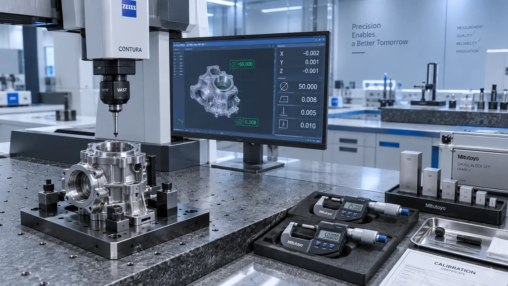
How to Select High-Precision Measuring Instruments for Tight-Tolerance Production?
High-precision measuring instruments are essential for tight-tolerance production. Learn how to evaluate accuracy, repeatability, environment, calibration, and data integration.
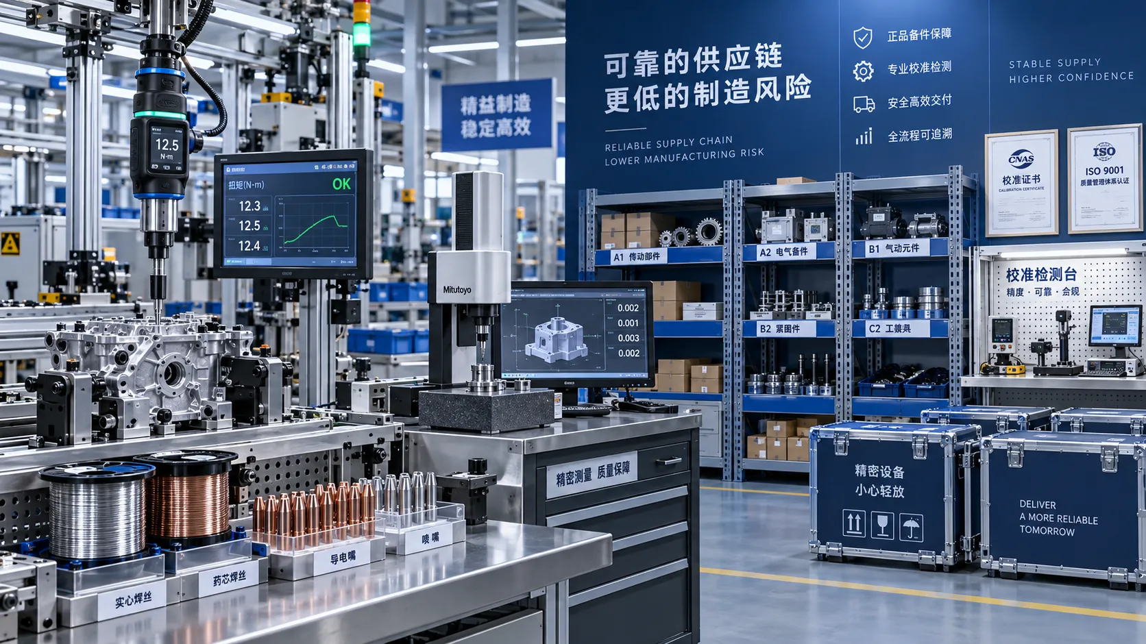
How Industrial Innovation Supplier Networks Reduce Sourcing Risk for Manufacturers
industrial innovation supplier network insights help manufacturers reduce sourcing risk, control lifecycle costs, and choose reliable tools, services, and suppliers with confidence.
Are Lower-Cost Metalworking Tools More Likely to Fail Early?
Are cheaper metalworking tools more likely to fail early? Explore duty cycle, build quality, and total ownership costs to make smarter buying decisions.

How Do Advanced Manufacturing Methods Improve Batch Consistency?
How do advanced manufacturing methods improve batch consistency? Discover how precision metrology, intelligent torque control, welding automation, and traceable data reduce variation and improve quality.

South East Asia Machine Tools Market: Demand Outlook by Manufacturing Industry
South East Asia machine tools market outlook: explore demand from automotive, electronics, fabrication, and infrastructure, plus smart sourcing priorities for manufacturers.
Related News
- 00
0000-00
Equipment Application Guidance for the Middle East: Managing Heat and Dust - 00
0000-00
Choosing an Industrial IoT Platform: Key Criteria for Legacy Equipment - 00
0000-00
How to Select High-Precision Measuring Instruments for Tight-Tolerance Production? - 00
0000-00
How Do Advanced Manufacturing Methods Improve Batch Consistency? - 00
0000-00
How to Prototype Electronic and Semiconductor Parts for Early Performance Testing
Prof. Marcus Chen
Weekly Insights
Stay ahead with our curated technology reports delivered every Monday.