
Optical Precision Metrology Explained: Key Accuracy Factors for Industrial Measurement





In many inspection rooms, the problem does not start with the instrument itself. It starts when a part “looks fine” on screen, but the reading changes after a fixture is reset, a room temperature drifts, or a different operator repeats the same measurement. That is where optical precision metrology becomes difficult to trust. The issue is not just getting a number; it is knowing whether that number can survive real production conditions.
For technical evaluators, this creates a familiar tension. A system may advertise sharp images and short cycle times, yet the actual decision depends on accuracy, repeatability, and process stability. If you are comparing optical measurement methods for manufacturing, aerospace, tooling, or maintenance work, the useful question is not “Can it measure?” but “What will disturb the result, and how should we control it?”
Where optical measurements usually go wrong
Most accuracy problems show up quietly. A dimension is measured from an edge that is not truly clean. A reflective surface creates a bright halo. A lens is slightly out of focus, so the software still finds a boundary, but not the right one. In some setups, the part is correctly captured, yet the measurement drifts because the machine, fixture, or environment changes between runs.
These issues are frustrating because they often look like operator mistakes. In practice, the root cause is usually a chain of small effects: lighting, part orientation, surface finish, calibration quality, thermal behavior, and algorithm settings. Optical precision metrology is sensitive to each of them, which is why a stable workflow matters as much as the hardware.
The accuracy factors worth checking first
Before changing tools or replacing software, it helps to review the factors that most often shape inspection performance.
1. Edge definition and surface behavior
Optical systems rely on contrast. If the edge is blurred by coatings, burrs, oil, glare, or texture, the detected boundary may shift. This is especially common on machined metals, polished components, and welded assemblies. A measurement can appear consistent at first glance while still being offset from the true feature.
The practical fix is to examine the part surface under the same lighting used for measurement. If the edge does not remain visually stable, the software probably has the same problem. Sometimes a change in illumination angle is enough; in other cases, the part needs cleaning or a different viewing strategy.
2. Lighting geometry
Lighting is not just brightness. Direction, diffusion, color temperature, and shadow control all affect how a feature is detected. Backlighting may work well for silhouettes, while coaxial or ring lighting may be better for reflective surfaces. The wrong light can hide the feature boundary or create false contours.
When a system behaves unpredictably, do not only increase exposure. Check whether the light shape matches the part geometry. A stable optical precision metrology setup usually depends on repeatable illumination more than raw intensity.
3. Focus, magnification, and field of view
It is tempting to maximize magnification for better detail, but that can shrink the field of view and make alignment harder. If the part moves slightly or sits at a different height, the measurement may shift. Poor focus can also soften edges enough to affect feature recognition.
A reasonable approach is to choose the lowest magnification that still resolves the feature clearly, then verify focus at the actual working height. If the process includes multiple part sizes, recheck whether one setup is being forced to cover too many conditions.
4. Calibration and traceability
Even a well-designed system loses credibility if calibration is treated as a formality. Reference artifacts, scale factors, and lens corrections must match the working range of the application. If calibration is done in one part of the range but used in another, the result can be technically neat and practically wrong.
For evaluators, the key point is traceability of the setup, not just the certificate attached to the device. Ask whether the calibration routine reflects the same optics, temperature range, and part geometry used in production.
5. Thermal and mechanical stability
Optical systems are often judged as “contactless,” which makes them seem immune to physical variation. They are not. Machine drift, fixture looseness, vibration, and ambient temperature changes can all alter the measurement path. A small shift in part position may matter more than the camera resolution itself.
If the result changes after warm-up, after lunch breaks, or when the shop floor gets busy, the environment deserves attention. Stable mounting, controlled warm-up routines, and consistent part clamping often improve repeatability more than software tuning.
Choosing the right way to verify a setup
When people compare systems, they often focus on the headline specification sheet. That is useful, but incomplete. A better comparison asks how each method handles real production variation. For example, can the system maintain focus across the full part height? Can it tolerate reflective finishes? Does it need constant operator intervention? Can the software explain why a feature was accepted or rejected?
Some teams use a structured trial: first inspect a known stable part, then vary one condition at a time, such as lighting angle, fixture position, or surface condition. This is a simple way to separate instrument limits from process problems. If the reading changes only when the setup changes, the issue is probably environmental. If it changes even when everything is controlled, the algorithm or optical path may need review.
At this stage, advanced metrology platforms are useful when they help make the process more transparent rather than more complex. Systems with clear parameter control, repeatable optics, and understandable inspection logic are easier to audit. That matters for technical evaluators, because the goal is not simply to collect measurements, but to defend them during review.
A practical workflow that reduces uncertainty
A reliable optical measurement workflow usually follows a simple pattern:
Start with the part surface. Remove obvious contamination, verify edge visibility, and confirm that the feature of interest is actually measurable in the chosen optical setup.
Then lock down the inspection environment. Keep lighting, fixture position, and working distance consistent. If the part must be reoriented, document the orientation instead of relying on memory.
After that, validate with repeated readings on the same setup. If the results move around, do not move straight to software changes. Check whether the variation comes from focus, clamping, or temperature.
Finally, compare the measured result against the tolerance question you really need answered. In many industrial cases, the issue is not maximum resolution; it is whether the system can separate acceptable parts from borderline ones without excessive false calls.
When a closer look is needed
There are times when internal troubleshooting is enough, and times when the measurement concept itself needs review. If the part surface is too reflective, the geometry is too complex, or the required tolerance sits near the edge of what the optical method can distinguish, no amount of small adjustment will fully remove uncertainty. That is when a broader evaluation of optics, fixturing, and software logic becomes necessary.
For industrial users, optical precision metrology works best when it is treated as a controlled measurement process, not a single device purchase. The more carefully you define the part condition, lighting, calibration, and stability requirements, the more useful the result becomes. In the end, accuracy is not only about seeing more detail; it is about seeing the right detail consistently.
Related News
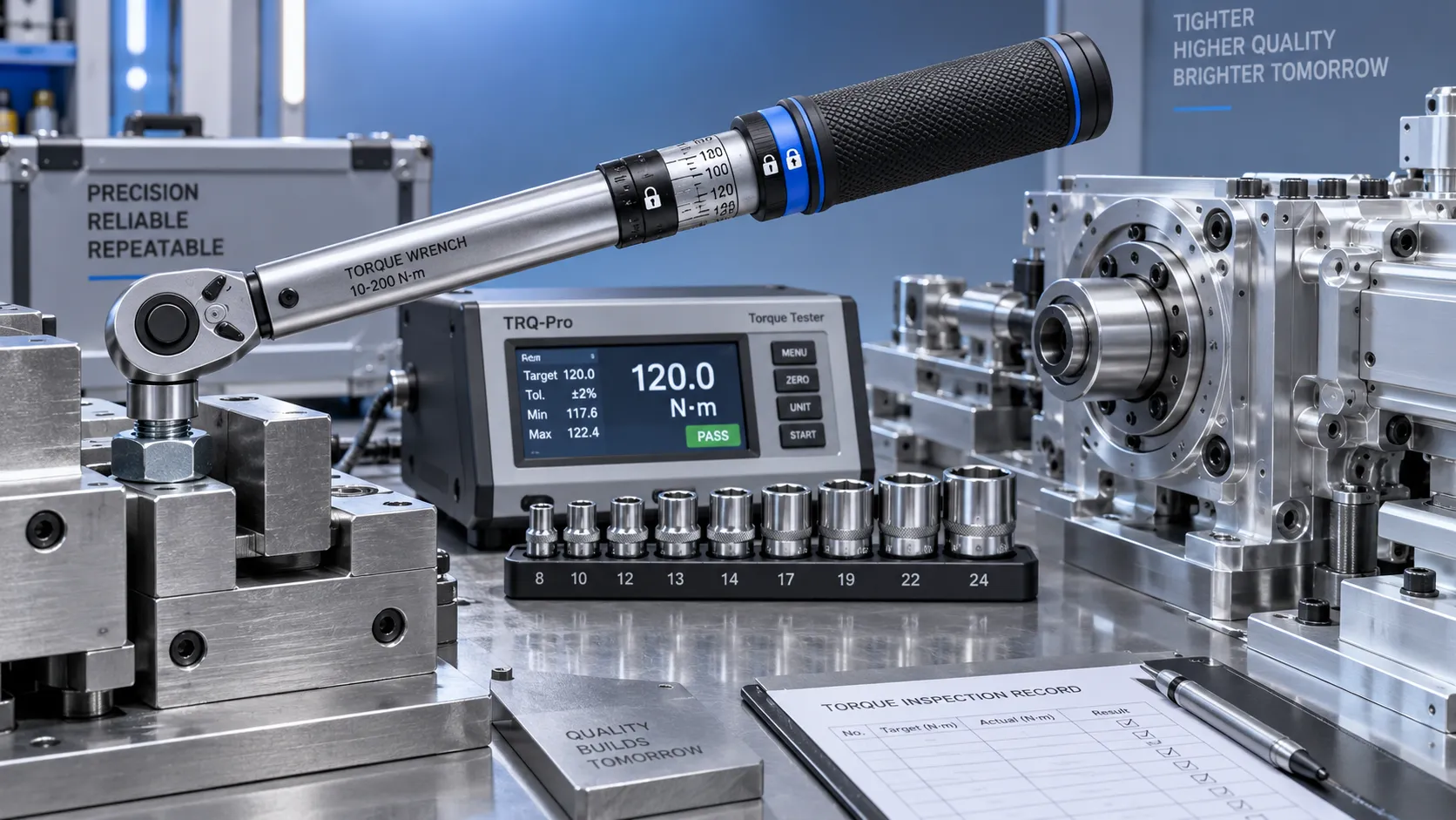
Selecting Adjustable Torque Tools for Repeatable Fastener Assembly
Adjustable torque tools: learn how to match range, accuracy, control methods, calibration, and ergonomics for repeatable, reliable fastener assembly.

How to Select Aerospace Inspection Tools for Aircraft Maintenance Tasks
Aerospace maintenance inspection tools: learn how to select reliable, traceable equipment for aircraft access, accuracy, calibration, and compliant maintenance decisions.
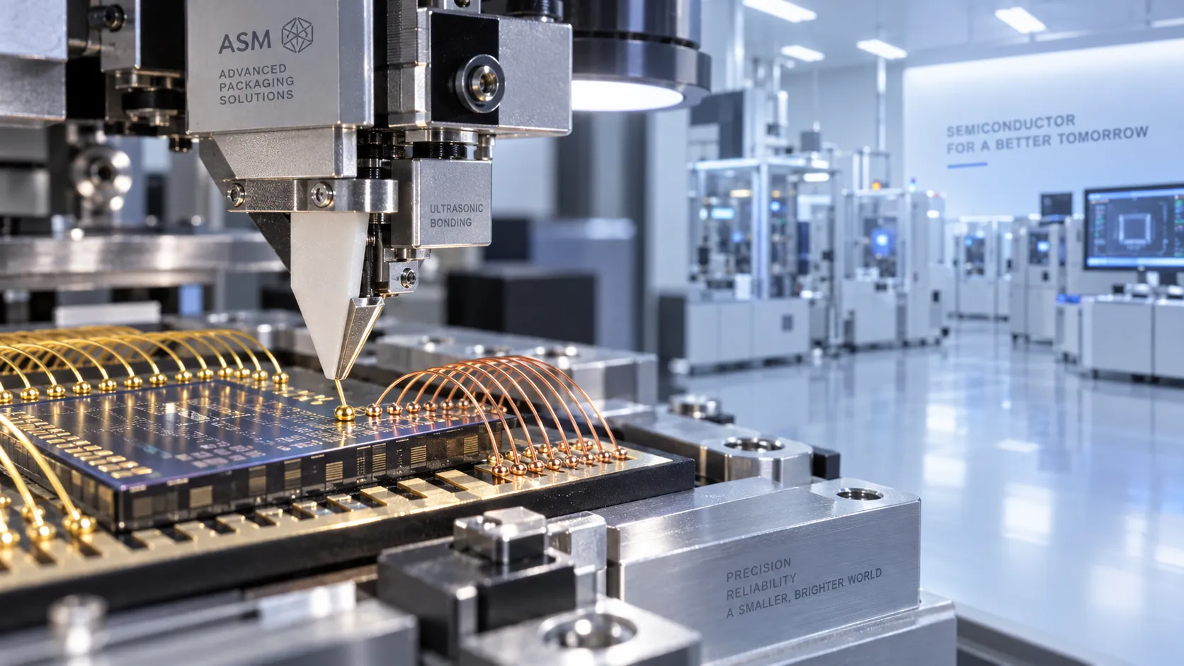
How to Select Wire Bonding Tools for Fine-Pitch Semiconductor Packaging
Explore semiconductor manufacturing tools for wire bonding and learn how to select precision solutions for fine-pitch packaging, reliable loops, accuracy, and yield.
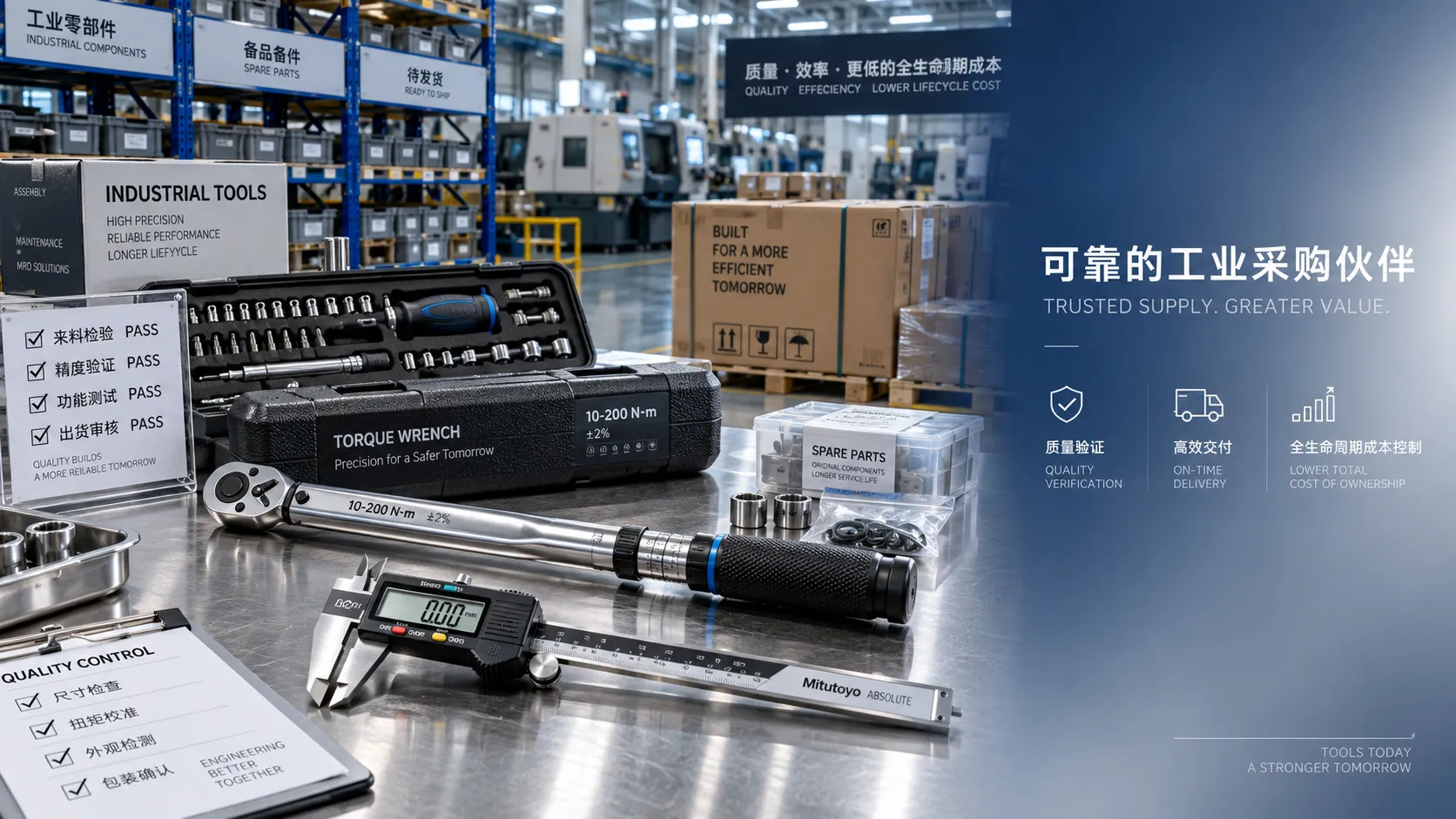
How to Compare Industrial Tool Suppliers for Quality, Lead Time, and Total Cost
Industrial tool selection supplier comparison made simple: evaluate quality, lead times, total cost, service, and supply resilience for confident sourcing decisions.

Industrial Equipment Application Guidance: Match Machines to Operating Conditions
Application guidance industrial equipment: match capacity, duty cycle, materials, site conditions, safety, and lifecycle cost to improve reliable output. Read the guide.
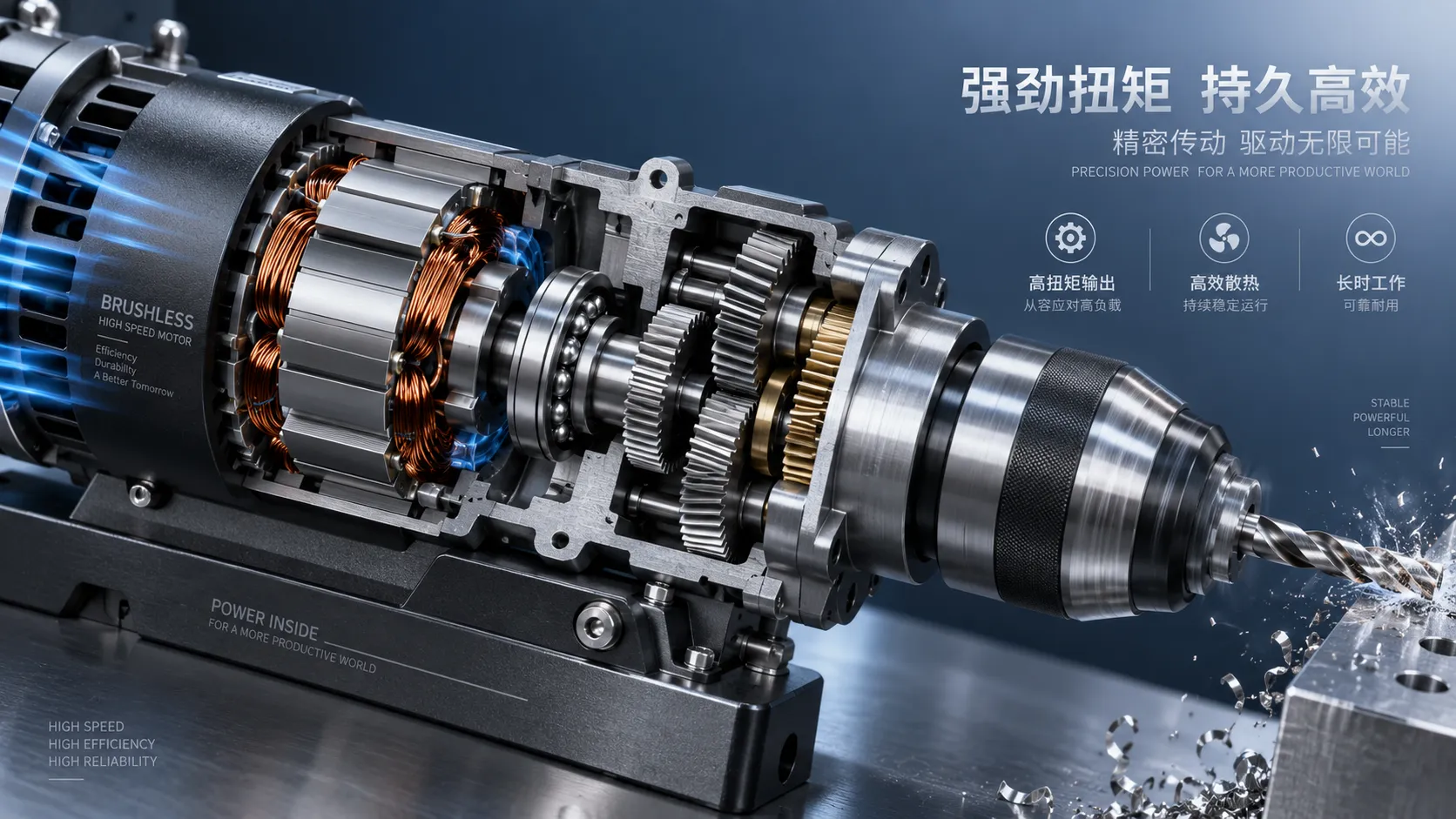
Selecting High-Speed Brushless Tool Motors for Torque, Heat, and Duty Cycle
High speed brushless tool motors: learn how to balance torque, heat, gearing, and duty cycle for reliable industrial tool performance and longer service life.
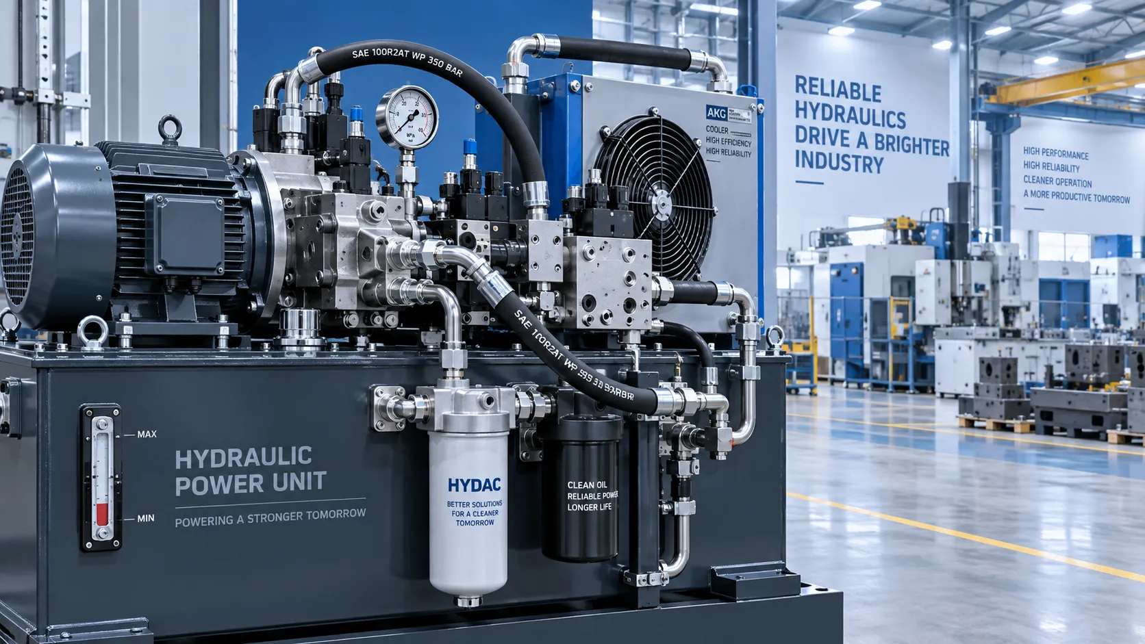
What Determines Industrial Hydraulic System Price for Heavy-Duty Equipment?
Industrial hydraulic system price depends on duty cycle, pressure, components, cooling, and integration. Compare quotes intelligently to secure reliable heavy-duty performance.

Welding Fume Extraction PPE: When Respirators Are Not Enough for Shop Safety
Welding fume extraction PPE: learn why respirators alone fall short and how source capture, ventilation, and layered controls improve shop safety.
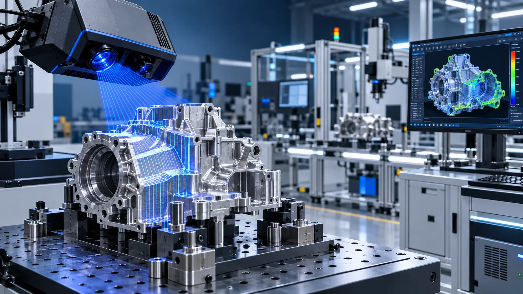
How to Select Optical Metrology Solutions for Tight-Tolerance Manufacturing
Optical industrial metrology solutions for tight-tolerance manufacturing: evaluate accuracy, surface compatibility, workflow, and traceability to select with confidence.
Related News
- 00
0000-00
Selecting Adjustable Torque Tools for Repeatable Fastener Assembly - 00
0000-00
How to Select Aerospace Inspection Tools for Aircraft Maintenance Tasks - 00
0000-00
How to Select Wire Bonding Tools for Fine-Pitch Semiconductor Packaging - 00
0000-00
Industrial Equipment Application Guidance: Match Machines to Operating Conditions - 00
0000-00
Selecting High-Speed Brushless Tool Motors for Torque, Heat, and Duty Cycle
Prof. Marcus Chen
Weekly Insights
Stay ahead with our curated technology reports delivered every Monday.