
Brushless Motors: Which Ratings Matter for Continuous-Duty Equipment?





Brushless Motors: Which Ratings Matter for Continuous-Duty Equipment?
A brushless motor can look excellent on a catalog page and still be the wrong choice for continuous-duty equipment. Peak power, no-load speed, and a compact frame may be relevant, but they do not answer the question that matters on a production floor: can the motor deliver the required output hour after hour without excessive heat, unstable control, premature bearing wear, or repeated shutdowns?
This distinction is especially important in industrial assembly tools, automated fastening stations, pumps, material-handling modules, welding auxiliaries, metrology fixtures, and compact hydraulic or electromechanical equipment. In these applications, a motor is part of a system. The driven load, gearbox, controller, cable length, ambient temperature, enclosure design, and operating profile all influence the real continuous capability.
For technical assessors, the useful task is not simply to compare motor nameplates. It is to determine whether the stated ratings were defined under conditions close enough to the intended application. A motor that survives intermittent overloads may be unsuitable for a machine that runs at moderate torque for an entire shift.
Continuous torque is more meaningful than peak torque
The first rating to examine is continuous torque. Peak torque is often technically valid, but it is commonly misunderstood. It describes the short-duration torque that the motor and controller may produce under specified conditions. It does not prove that the same torque can be held indefinitely.
In a brushless DC motor or permanent-magnet synchronous motor, torque is closely related to current. More torque generally means more current, and current creates copper losses that rise with the square of current. A modest increase in load can therefore create a disproportionate thermal burden. If the tool is driving a stiff fastening joint, operating a feeder, or maintaining force in a clamping mechanism, the continuous current requirement deserves more attention than the short peak available during acceleration.
Ask for the torque-speed curve and identify the part of the curve supported continuously, not merely briefly. The relevant operating point should include gearbox losses and any torque multiplication or reduction caused by transmission components. A quoted motor torque is not automatically the usable spindle or output-shaft torque.
For variable-load machinery, an RMS torque calculation is often more useful than a single maximum-load figure. RMS torque reflects the heating effect of a duty profile that includes acceleration, loaded running, deceleration, dwell periods, and recurring overload events. The calculation should be based on the actual cycle, including the worst credible production pattern rather than an idealized average.
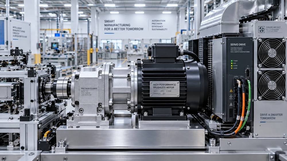
Thermal ratings determine whether “continuous” is real
Thermal performance is where many motor comparisons become unreliable. A continuous rating depends on an allowable winding temperature rise, the ambient temperature assumed by the manufacturer, the cooling method, mounting arrangement, and the ability of the surrounding machine to shed heat. If any of those conditions change, the continuous output may need to be reduced.
A motor mounted inside a sealed tool housing will behave differently from the same motor tested on an open bench. Forced-air cooling can improve capacity, but only if airflow remains available when filters load, fans age, or the tool is placed in a confined enclosure. Liquid cooling introduces another set of dependencies: coolant temperature, flow, hose routing, leak prevention, and maintenance discipline.
The insulation system rating is also relevant, but it should not be treated as permission to run continuously at the highest possible winding temperature. High temperatures can affect magnet strength, winding insulation life, adhesive systems, lubricants, sensors, and nearby electronics. Permanent magnets are particularly worth reviewing when sustained heat or high fault current could approach the motor’s temperature limits.
Technical evaluations should request the thermal basis behind a stated continuous power figure: ambient reference temperature, temperature-rise method, cooling condition, mounting condition, and derating rules. Standards in the IEC 60034 family are often relevant to rotating electrical machines, but applicability depends on the motor type, market, and equipment category. A supplier’s test method should be reviewed alongside—not assumed to replace—the requirements that govern the finished machine.
Efficiency is a map, not one number
A headline efficiency figure can conceal a poor fit. Brushless motors are often efficient across a useful operating range, yet the highest efficiency point may occur at a speed and load far from the intended duty point. In continuous operation, the shape of the efficiency map matters because every loss becomes heat that must leave the motor, gearbox, inverter, or enclosure.
Evaluate efficiency at expected torque and speed combinations. Low-speed, high-torque operation can be demanding because current is high while the motor’s own fan, if present, may provide little cooling. Operating at very high speed can introduce iron losses, bearing losses, acoustic concerns, and limits in the inverter’s switching or voltage capability. The apparently simple solution of selecting a larger motor may also create poor low-load efficiency, excess inertia, or control difficulties.
System efficiency matters more than motor efficiency alone. The controller’s conduction and switching losses, cable losses, power-supply conversion efficiency, brake losses, and gearbox efficiency should be included when energy use or enclosure heating is important. In battery-powered industrial tools, this system view has an immediate effect on runtime and battery temperature. In permanently installed equipment, it affects electrical sizing and thermal management.
Duty cycle needs a precise definition
“Continuous duty” is sometimes used loosely to mean that a machine is intended for regular production use. For motor selection, it needs a more exact meaning. Is the shaft rotating continuously? Is torque constant? Are there repeated starts and stops? Does the motor hold position between cycles? Is there a cooldown interval that disappears when output rises?
A station that runs for twenty seconds and rests for forty seconds is thermally different from one that runs continuously, even if both achieve the same hourly output under certain conditions. Conversely, frequent starts can be harder on the motor and drive than steady rotation because acceleration requires additional current. Repeated reversing, regenerative braking, and high-inertia loads should be considered separately from steady-state shaft power.
The duty description should cover cycle time, load torque, speed, acceleration, dwell, direction changes, expected utilization, ambient temperature, and the number of cycles expected over the equipment life. A meaningful review also considers abnormal but foreseeable conditions: a jammed feeder, a partially stalled tool, blocked ventilation, or a production line operating above its original shift pattern.
Controller capability cannot be separated from motor ratings
Brushless motors depend on electronic commutation, so their practical rating is inseparable from the controller. The inverter must provide adequate continuous current, not only a short peak current. It must also handle the supply voltage range, switching frequency, regenerative energy, sensor interface, and required control mode.
Sensorless control may be acceptable for a fan or pump operating above a predictable speed. It can be less suitable where reliable starting torque, low-speed stability, precise positioning, or controlled torque at standstill is required. Hall sensors, encoders, resolvers, or other feedback arrangements add cost and integration work, but they may be necessary for repeatable assembly processes and intelligent torque control.
Protection settings need careful coordination. Current limits protect power electronics and windings, while thermal protection responds to accumulated heating. A controller that trips too quickly can reduce machine availability; one that permits excessive current for too long can shorten motor life. If the system includes a gearbox, its torque limit may be lower than the motor’s peak capacity. The weakest continuous component should set the operational boundary.
Environmental ratings are operational ratings
Ingress protection, corrosion resistance, vibration tolerance, and bearing design are not secondary details in continuous-duty equipment. An IP rating indicates a defined level of protection against solid objects and water under specified test conditions; it should not be read as a blanket statement of suitability for washdown chemicals, abrasive dust, welding fume, conductive particles, or outdoor temperature cycling.
Brushless motors used near metal finishing, welding, or machining may face contamination that enters through connectors, cooling paths, and shaft seals rather than the motor housing alone. Sealed motors can reduce contamination exposure, but sealing may also restrict cooling. That trade-off should be resolved using the real thermal load rather than a preference for the highest IP number.
Bearings deserve the same scrutiny. Radial and axial load limits, shaft orientation, belt tension, coupling alignment, vibration, and grease life all influence service intervals. A motor selected solely by electrical capacity can fail mechanically if the driven arrangement imposes side loads beyond its bearing design. Where a gearbox is integrated, assess lubrication life, backlash requirements, shock loading, and whether maintenance access matches the machine’s planned service strategy.
A practical rating review before release
A disciplined review usually produces better decisions than comparing nominal watts. Before approving brushless motors for continuous service, technical teams should be able to answer several specific questions:
- What torque and speed are required at the real output shaft across normal, maximum, and transient conditions?
- Is the stated torque continuous, intermittent, or subject to a particular cooling and ambient condition?
- What are the expected RMS current and RMS torque over the actual duty cycle?
- Can the controller sustain the required current and manage regenerative energy without repeated fault events?
- What temperature feedback, derating logic, and fault response are available in the finished assembly?
- Do housing, connectors, cables, bearings, and geartrain withstand the relevant contamination, vibration, and maintenance conditions?
This type of review is increasingly relevant as industrial tools become lighter, more connected, and more electronically controlled. A compact motor may support a better ergonomic design, but only if heat, control stability, and tool balance remain acceptable during extended use. Likewise, connected torque tools can generate valuable process data, yet the quality of that data depends on stable sensing, calibrated control behavior, and a motor-drive system that does not drift into thermal limiting during production.
From nameplate comparison to lifecycle judgment
The most dependable continuous-duty motor selection starts with the load profile and works backward to the motor, drive, cooling arrangement, and protection strategy. It does not start with maximum power. Where the application is still being defined, a thermal test on the assembled equipment is often more revealing than motor-only calculations, particularly for sealed tools, compact enclosures, and processes with recurring overloads.
GPTWM’s Strategic Intelligence Center follows this intersection of motor efficiency, industrial tool design, and intelligent torque control because it is a recurring “last mile” manufacturing issue: a capable component must still perform inside a real machine, in a real environment, over a realistic service interval. For assessors, the useful next step is to document the actual operating envelope and request rating evidence against it. Continuous torque, thermal limits, efficiency at the duty point, controller capacity, and environmental fit should all agree before a brushless motor is treated as a continuous-duty solution.
Related News
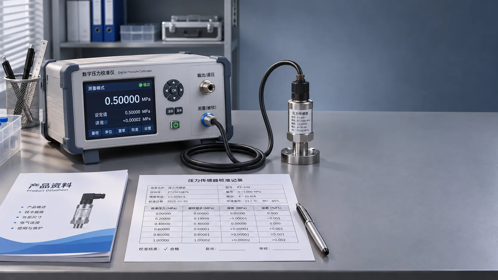
Calibration Tool Specifications: Where to Find and Verify Product Data
Explore product information resources for calibration tools and learn how to verify specifications, certificates and traceability before you buy.
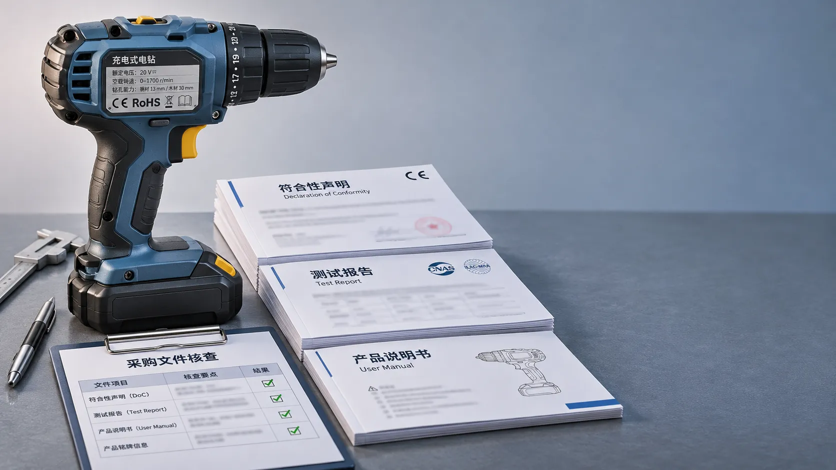
Choosing CE-Marked OEM Tools: Documents Buyers Should Check
Buying OEM tool solutions CE certified for Europe? Discover the documents to check, avoid costly compliance gaps, and choose suppliers with confidence.
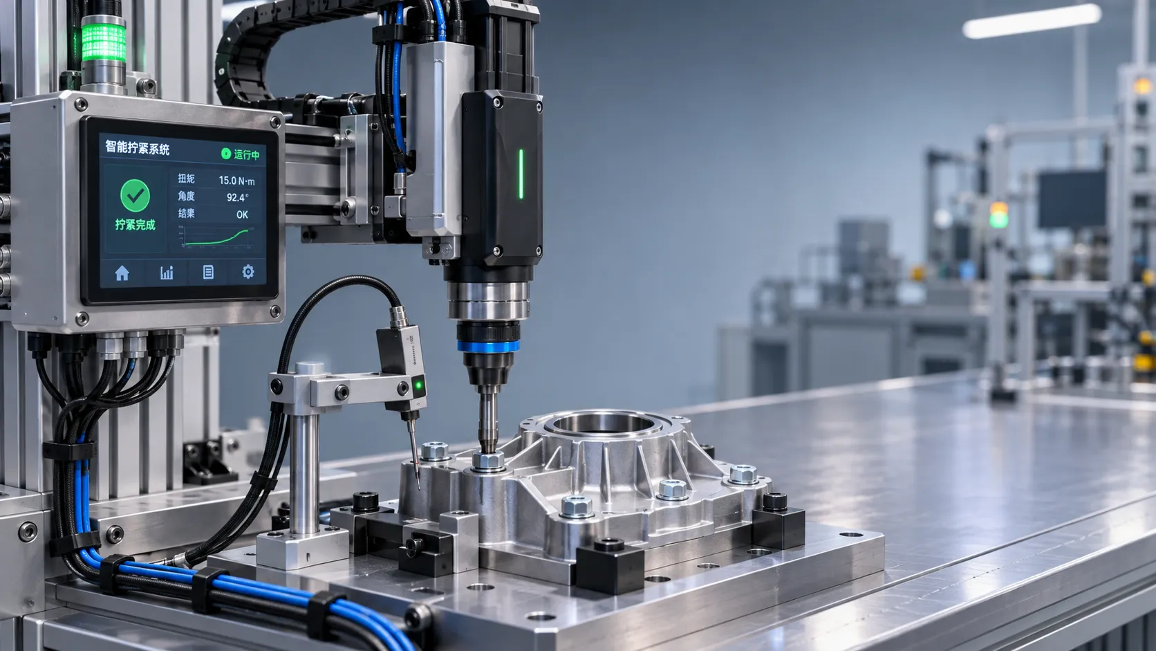
Industrial Innovation Trends: Where Manufacturers Should Invest
Explore industrial innovation trends in fastening, metrology, laser welding, and connected tools—and discover where manufacturers should invest.
Industrial Assembly Specifications: How to Define Tolerances and Torque
Explore specification-oriented articles on industrial assembly and learn how to define tolerances, validate torque settings, and improve joint reliability.
AMS Specifications for Aerospace Tooling: What Do They Cover?
Aerospace tools AMS requirements can cover materials, processes and documentation. Learn how to verify compliance and assess finished-tool acceptance.
Choosing Industrial Assembly Solutions for High-Mix Production Lines
Choose industrial assembly solutions for high-mix production with practical guidance on changeovers, quality, traceability, automation, and total cost.
Choosing an Industrial IoT Tools Distributor: Integration and Support Criteria
Choose an industrial IoT tools distributor with confidence. Compare integration, support, security, and lifetime costs to avoid hidden risks and protect production.
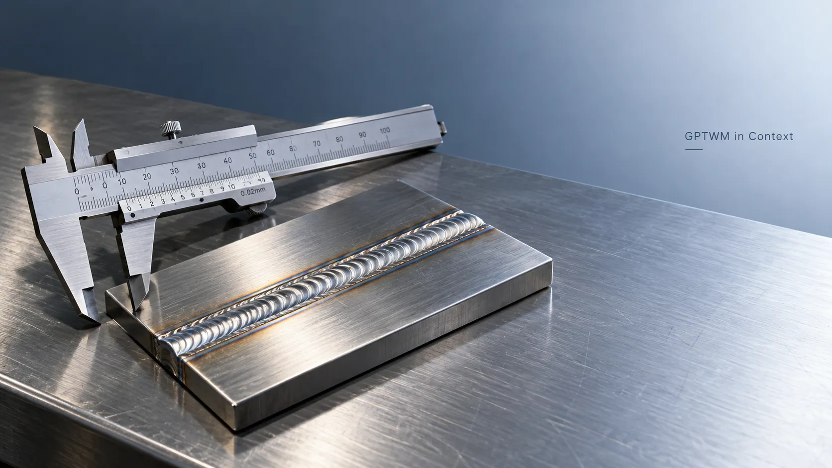
What Does GPTWM Mean? How to Verify Its Meaning in Context
What does gptwm mean? Explore its industrial context and learn how to verify the full name, publisher, and supporting sources before relying on its claims.
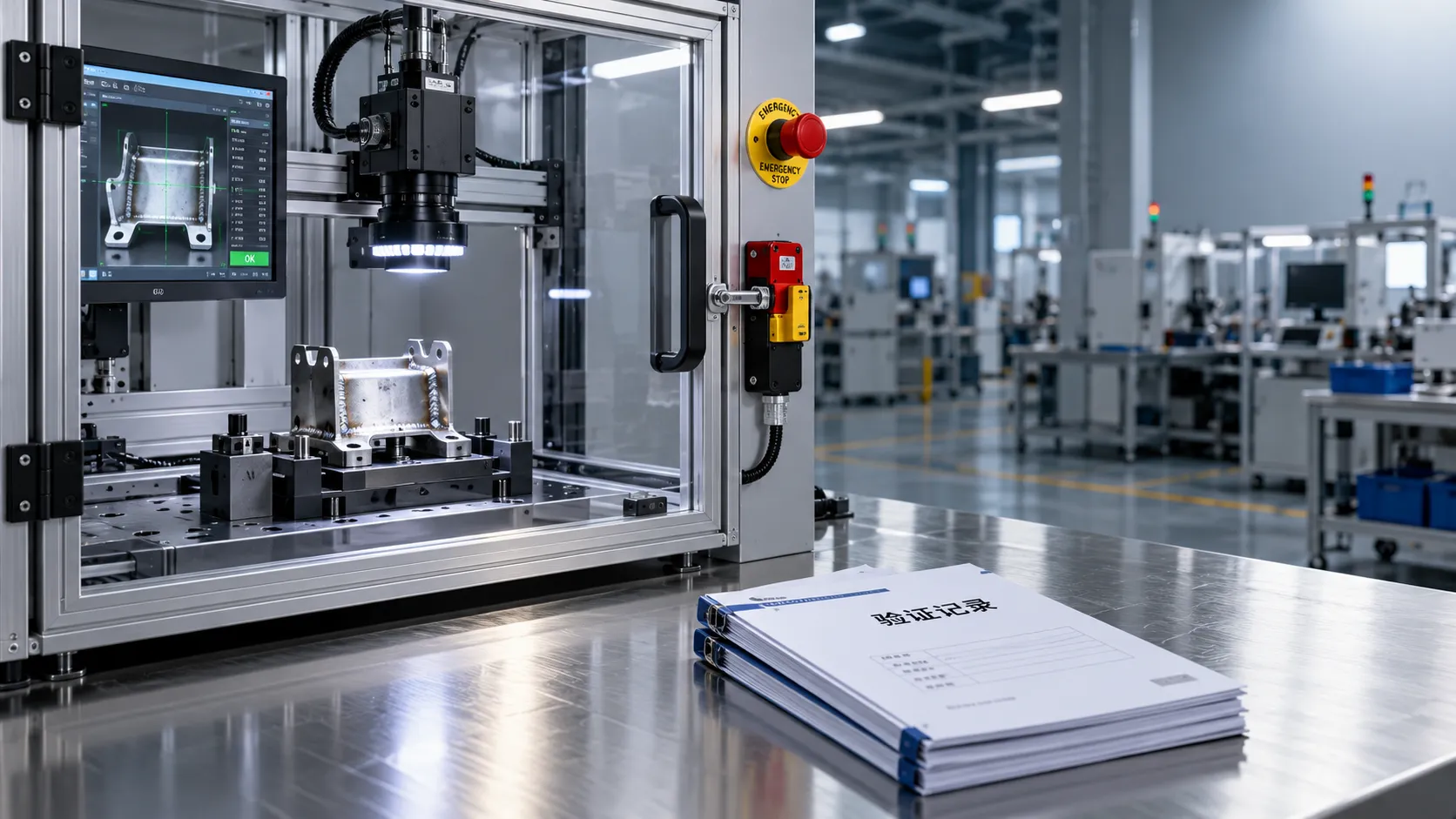
Industrial AI Compliance Guide: What to Check Before Factory Deployment
Use this industrial intelligence compliance guide to check safety, legal duties, cybersecurity, and validation before factory AI deployment. Explore the checklist to close critical gaps.
Related News
- 00
0000-00
Brushless Motors: Which Ratings Matter for Continuous-Duty Equipment? - 00
0000-00
How to Select Battery Assembly Tools for Torque Control and High-Volume Production - 00
0000-00
How Battery, Torque, and Duty Cycle Affect Cordless Power Tool Efficiency - 00
0000-00
How to Size High-Torque Tool Motors for Continuous-Duty Assembly Lines - 00
0000-00
How to Choose 24V Brushless Tool Motors for Torque, Runtime, and Duty Cycle?
0000-00
Electro-Mech Tool Designer
Weekly Insights
Stay ahead with our curated technology reports delivered every Monday.