
Precision Measuring Instruments for Toolmaking: Selecting for Tight Tolerances





Select precision measuring instruments for toolmaking by starting with the feature, its tolerance, and the conditions under which it will be accepted. A micrometer can be the strongest choice for a simple external dimension, while a coordinate measuring machine may be necessary for a feature defined relative to several datums. Neither choice is defensible until the complete measurement method can distinguish acceptable work from unacceptable work with sufficient confidence.
For tight tolerances, the instrument’s display resolution offers little assurance on its own. Selection should establish whether measurement uncertainty is appropriate for the tolerance, whether the setup represents the drawing requirement, and whether operators can reproduce the result. These conditions determine whether a purchase improves inspection capability or simply produces more decimal places.
Define the acceptance task before comparing instruments
A purchasing specification that asks only for measuring range and accuracy leaves important decisions unresolved. Consider a hardened punch: its outside diameter, roundness, taper, and position relative to a mounting feature are different inspection tasks. A two-point micrometer can measure local diameters, but a few readings cannot establish the full surface geometry or the relationship between features.
Begin with the drawing and identify exactly what must be verified. Record the tolerance limits, datum references, material, surface condition, accessibility, and inspection stage. Measurements taken before heat treatment or final grinding may support process control without providing sufficient evidence for final acceptance.
Geometry often narrows the instrument shortlist more quickly than the tolerance value. Deep bores require suitable reach and alignment control. Thin walls may deform under contact force. Narrow grooves need contacts that reach the intended surfaces without bridging adjacent edges. Small radii and polished cutting edges may require optical access because a physical probe cannot contact the feature reliably.
Also distinguish between measuring a value and making a production decision. During tool development, engineers may need dimensional data to diagnose machining errors. For repeated acceptance of an established feature, a dedicated comparator or functional gauge may provide a faster, more consistent decision. Its suitability still depends on what it checks and what defects it could miss.
Build the uncertainty requirement around the decision
Resolution is the smallest displayed increment. Repeatability describes agreement under repeated measurement conditions. Instrument accuracy specifications describe performance within stated conditions, while calibration establishes relationships to reference values and reports associated uncertainty. None of these, taken alone, describes the uncertainty of measuring a particular tool in a particular setup.
The measurement process also includes the reference standard, fixture, alignment, temperature, contact force, surface finish, operator technique, and sampling strategy. A favorable calibration certificate cannot compensate for a flexible stand or a workpiece measured while still cooling after grinding. Technical evaluation should therefore consider the complete method, including contributions that arise outside the instrument.
An uncertainty budget need not begin as an elaborate document. Start by identifying the contributions likely to affect the acceptance decision. Use calibration information, repeat measurements, environmental observations, and justified estimates to evaluate them. Combining these contributions requires a consistent treatment of uncertainty; simply adding catalog accuracy, resolution, and repeatability figures can produce a misleading result.
A tolerance-to-uncertainty ratio can help screen candidate methods, provided its definition is explicit. Dividing the full tolerance width by expanded measurement uncertainty gives a different result from dividing it by the full width of the uncertainty interval. Procurement documents should state the convention, coverage assumptions, and required decision rule. A ratio without those details is difficult to interpret and easy to compare incorrectly.
Consider an illustrative dimension specified as 20.000 ±0.005 mm. A reading of 20.004 mm with expanded uncertainty of 0.002 mm lies inside the drawing limits, but its associated uncertainty interval crosses the upper limit. Whether the part is accepted depends on the agreed decision rule. A guard band can reduce false acceptance risk by moving the acceptance boundary inward, although it also increases the possibility of rejecting conforming parts.
Agree on this treatment before ordering equipment. A method that works for adjusting a grinding process may leave too much ambiguity for final release near the specification limits. When uncertainty consumes too much of the available tolerance, improvement may require better temperature control, different fixturing, or a more suitable measurement principle rather than a finer display.
Choose instruments according to the feature they can verify
Micrometers are strong candidates for accessible external sizes, thicknesses, and selected internal dimensions when the contact geometry matches the feature. Evaluate anvil shape, parallelism, measuring force, frame behavior, and handling. A force-limiting mechanism improves consistency, but the operator must still align the contacts correctly and avoid introducing heat through prolonged handling.
For thin sections, narrow lands, or soft materials, standard flat anvils may produce a misleading reading through deformation or unintended contact. Blade, ball, or other specialized contacts can improve access, but they change how the measurement is made and verified. Confirm performance with the actual contact configuration. For a cylindrical feature, measurements at several positions can reveal variation, although they do not replace a dedicated assessment of form when the drawing requires one.
Indicators and comparators are useful for alignment, runout checks, and detecting small deviations from a reference. Their performance depends heavily on the supporting structure and measurement geometry. A sensitive indicator on a flexible arm can respond to fixture movement as readily as to part variation. Lever-type indicators also require attention to contact angle because the setup can introduce cosine error.
Keep size, form, and runout requirements separate. An indicator showing a small variation as a component rotates does not independently establish its diameter or fully describe its roundness. The result reflects the workpiece, rotational setup, datum establishment, and contact position. For comparative size measurement, a suitable master and stable fixture can make an indicator-based system effective over a limited range.
Height gauges suit work involving shoulders, steps, and feature heights referenced to a surface plate. The plate, probe, part support, and operator technique are part of the measuring system. Burrs beneath a component, contamination, rocking, or an unsuitable contact direction can undermine results even when the gauge itself performs well. For hole centers or derived features, examine how the instrument constructs the result and whether that method matches the drawing.
A height gauge becomes less attractive when the inspection requires repeated reorientation or several datum relationships that are difficult to preserve. Each setup can introduce additional uncertainty and opportunities for error. A coordinate system may then provide a more practical workflow, provided its access, probing strategy, and task-specific performance are adequate.
Coordinate measuring machines are valuable when a tool contains multiple related features, complex geometry, or geometric tolerances tied to a datum reference frame. Their ability to collect coordinates does not automatically establish capability for every tight tolerance. Probe configuration, stylus length, access, alignment, sampling, and evaluation software all influence the result.
A machine specification is a starting point for evaluation. Ask how the proposed system will inspect the difficult features: a deep bore, a small-radius transition, or a critical feature far from the datum may challenge it differently. Sparse sampling can miss local form deviations, while fitting and filtering choices can change reported geometry. Acceptance programming deserves the same technical scrutiny as the hardware.
Optical systems can help with fragile edges, small profiles, and features that resist reliable tactile probing. Evaluate lighting, focus, edge detection, surface reflectivity, and the relationship between the visible edge and the specified geometry. A stable image can still produce an unsuitable dimensional result if the detected boundary changes with illumination or does not represent the intended feature.
These methods often complement one another. A toolroom may use micrometers for routine size checks, indicators for setup and adjustment, and coordinate or optical measurement for relationships and profiles. The useful comparison is the capability and cost of the complete inspection route, including any measurements needed to cover features the primary instrument cannot verify.
Test capability where the instrument will be used
Temperature deserves early attention because the tool, instrument, master, and fixture may all change dimension. Differences in material and temperature can create errors that do not cancel. A workpiece brought directly from machining may also contain temperature gradients, making simple compensation inadequate. Establish stabilization conditions and handling practices that are practical for the intended inspection location.
Cleanliness and mechanical stability deserve equal attention. Oil films, chips, burrs, and contaminated contacts can shift readings. Vibration, compressed-air disturbances, or movement in a bench can affect sensitive setups. Environmental protection ratings can help assess resistance to exposure, but they do not demonstrate measurement capability under those conditions.
A supplier demonstration should use representative parts and the proposed fixtures, probes, and software. Include features near the limits of access and range, along with examples close to acceptance boundaries. A favorable result on an easy reference artifact provides limited evidence for a difficult production measurement.
A practical evaluation should examine:
- Repeated measurements after complete removal and repositioning of the part.
- Agreement between trained operators using the same documented method.
- Performance after normal warm-up, handling, and expected temperature changes.
- Agreement with an appropriate reference method whose uncertainty is understood.
- Total inspection time, including cleaning, stabilization, setup, and reporting.
Repeatability alone is insufficient: a method can produce closely grouped readings with a systematic error. Where possible, investigate discrepancies against the reference method and account for uncertainty in both results. For repeated production measurements, a measurement system study can help separate equipment and operator contributions. Its design should reflect the parts and tolerance being evaluated; a small spread between sample parts can make some study metrics difficult to interpret.
Calibration traceability must support the working configuration and relevant range. Review reported uncertainty, calibration points, corrections, and limitations. Specialized contacts or long styli may require additional verification. Set recalibration intervals using usage, handling risk, intermediate checks, and observed stability. For demanding measurements, a fixed calendar interval by itself offers little evidence that performance remained acceptable between calibrations.
Make the purchase conditional on a usable inspection method
Compare total operating cost after capability is established. Include masters, fixtures, probe replacement, calibration, software, training, maintenance, and the time required to produce a defensible result. A dedicated comparator may offer better throughput for one repeated dimension, while a flexible coordinate system may justify its cost across a changing mix of tools.
The purchase specification should identify the critical features, operating conditions, uncertainty expectations, decision rule, representative-part demonstration, and required records. It should also define who owns the measurement procedure and how changes to fixtures, probes, or software will be controlled. Delivery of the instrument is only one part of acceptance.
If the proposed method cannot confidently resolve results near the tolerance boundary, establish a reference route before release decisions begin. That may involve controlled laboratory inspection or a more capable method for borderline results. Giving those parts a defined path prevents operators from treating an extra decimal place as permission to accept them.
Related News
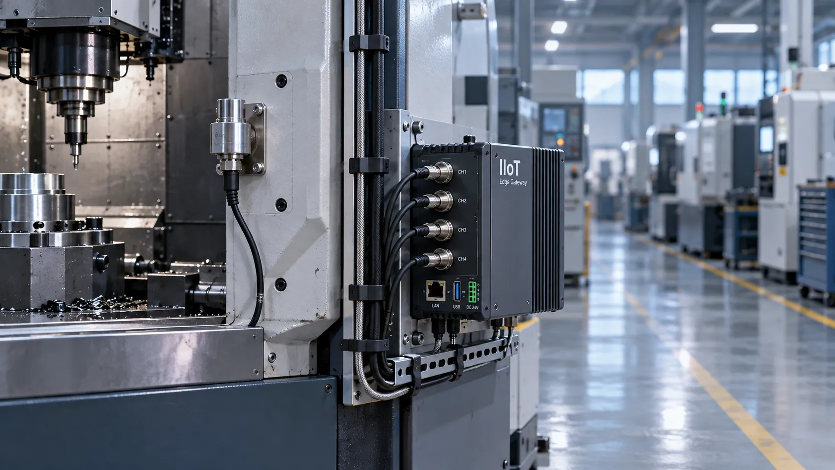
Evaluating Industrial Intelligence Solutions for Legacy Equipment Integration
Evaluate industrial intelligence solutions for legacy equipment. Discover how to verify compatibility, protect production, and compare lifecycle costs before investing.

ADAS Calibration After Vehicle Maintenance: Which Jobs Require It?
Automotive maintenance calibration: Learn which repairs may require ADAS recalibration, from windshield replacement to alignment, and how OEM guidance helps you avoid costly mistakes.

Laser vs. Resistance Spot Welding: Which Fits Automotive Body Assembly?
Choosing welding technology for automotive body assembly? Compare laser and resistance spot welding on joint access, quality, cycle time, and cost to find the right fit for your production line.
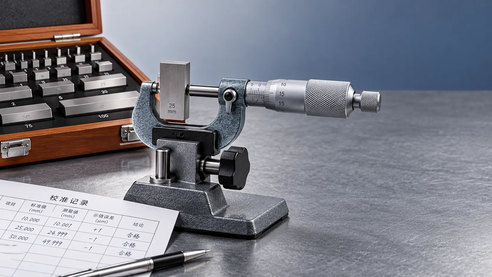
Choosing a High-Precision Measuring Instrument Supplier: Calibration and Support
Choose a high-precision measuring instruments supplier with confidence. Discover how to verify calibration, compare support, and control lifecycle costs before you buy.
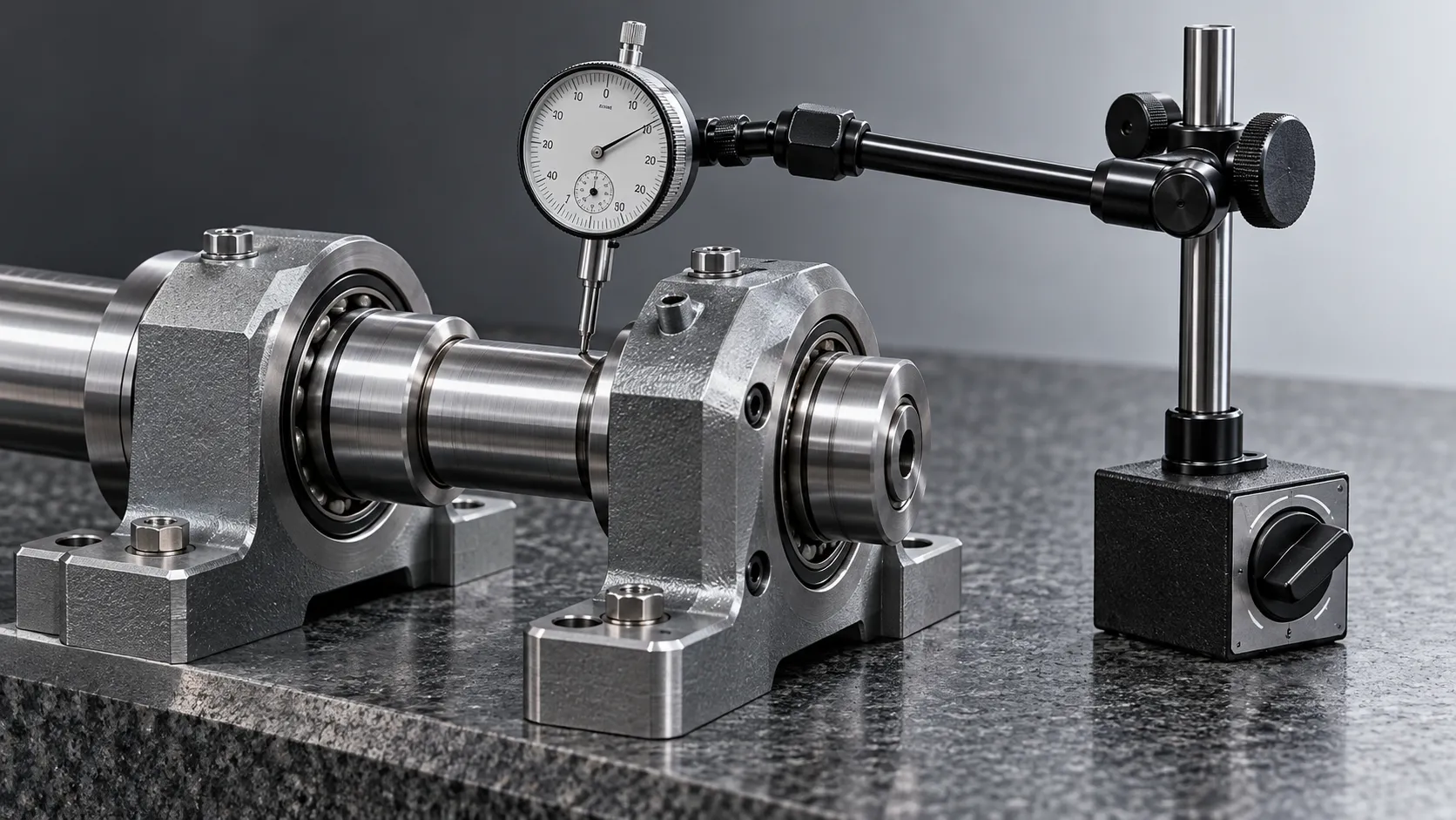
What Defines Craftsmanship in Metalworking? Fit, Finish, and Precision
Discover what defines craftsmanship in metalworking: fit, finish, and precision. Learn how to spot quality, assess suppliers, and choose parts that perform reliably.
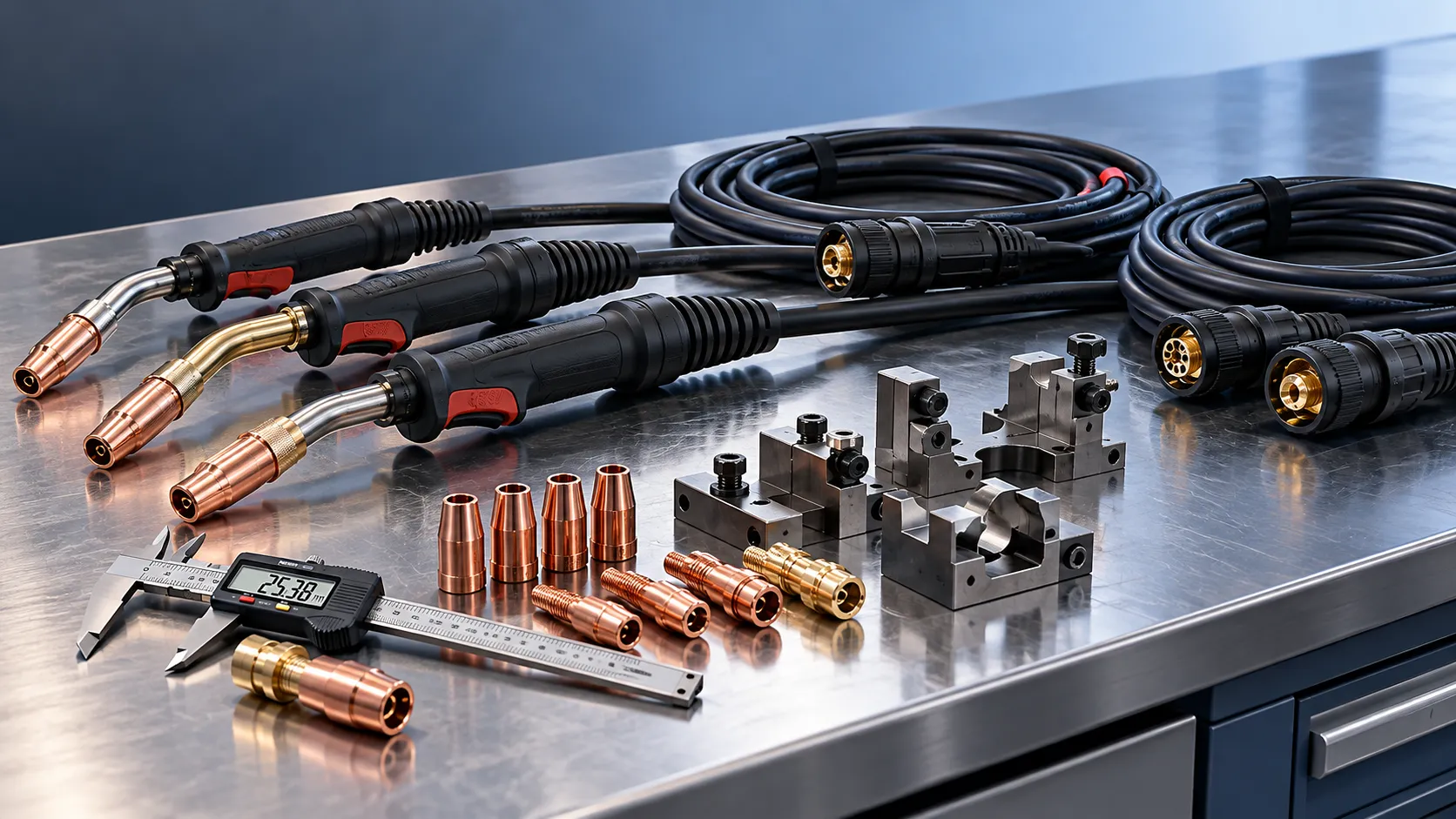
Choosing a Welding Tools Manufacturer: Quality Checks Before a Bulk Order
Choosing a welding tools manufacturer? Discover essential quality checks, sample tests, and inspection terms to reduce bulk-order risks and buy with confidence.
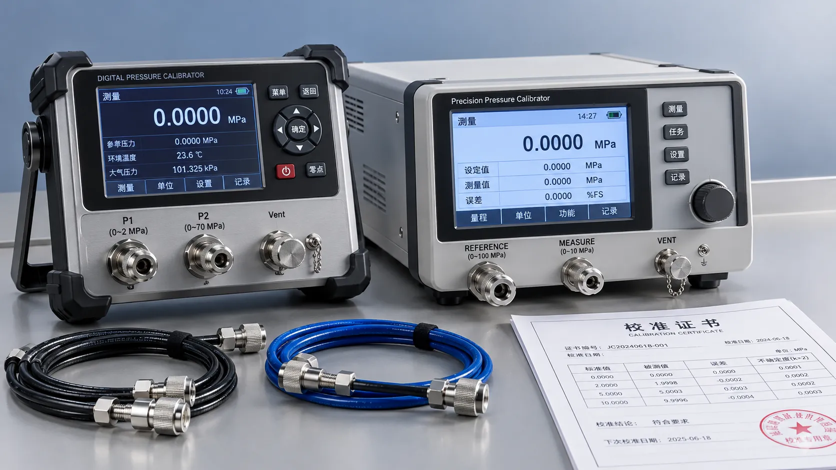
How to Compare Calibration Tools: Range, Uncertainty, and Traceability
Explore product comparison resources for calibration tools. Compare range, uncertainty, and traceability to choose confidently and support defensible measurement decisions.
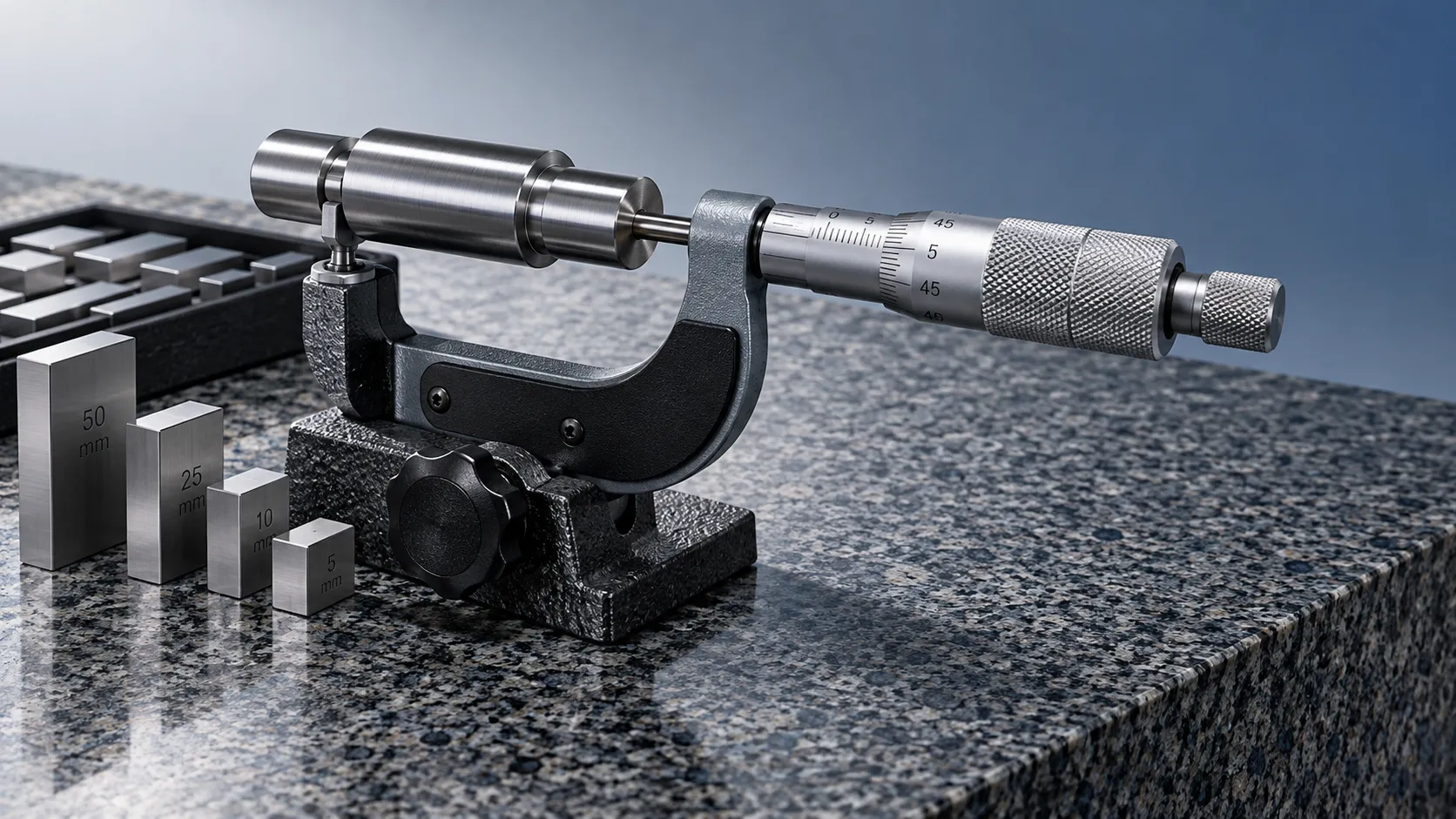
Choosing Industrial Metrology Tools: Matching Measurement Uncertainty to Tolerances
Improve industrial tool selection for metrology by matching measurement uncertainty to tolerances. Learn how to reduce inspection risk and choose equipment with confidence.
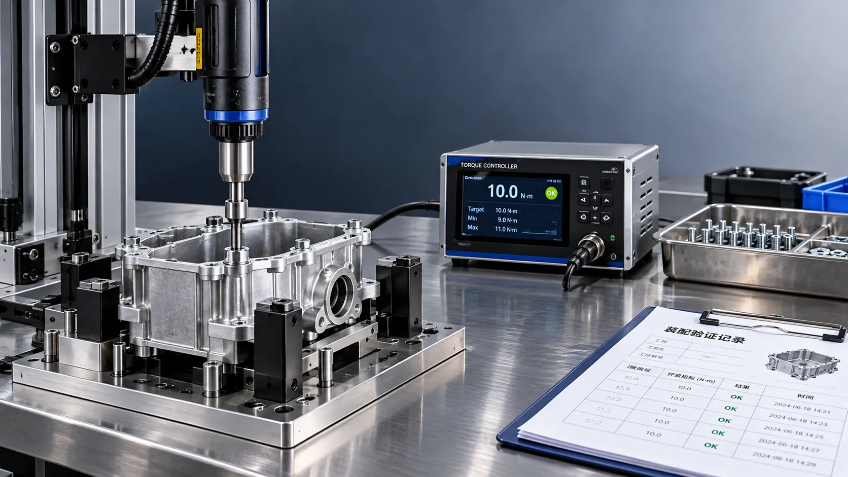
Torque System Suppliers: How to Assess References for Assembly Projects
Explore supplier and solution references torque systems buyers should verify. Assess assembly fit, traceability, and support to reduce risk and choose with confidence.
Related News
- 00
0000-00
Precision Measuring Instruments for Toolmaking: Selecting for Tight Tolerances - 00
0000-00
How to Compare Calibration Tools: Range, Uncertainty, and Traceability - 00
0000-00
Choosing Industrial Metrology Tools: Matching Measurement Uncertainty to Tolerances - 00
0000-00
How Often Should Precision Measuring Instruments Be Calibrated? - 00
0000-00
Which Precision Measuring Tools Are Best for Incoming Inspection?
0000-00
Metrology Fellow
Weekly Insights
Stay ahead with our curated technology reports delivered every Monday.