
Laser vs. Resistance Spot Welding: Which Fits Automotive Body Assembly?





A body-in-white line can have two very different joining problems: a reinforcement stack that must tolerate normal stamping variation, and a roof joint where flange width, appearance, and tool access constrain the design. Resistance spot welding is usually the stronger starting point for accessible lap joints in established high-volume production; laser welding becomes attractive where one-sided access, narrow joint geometry, or seam-based structural performance justifies tighter process control. Choosing incorrectly can shift costs into fixtures, inspection, rework, or lost station availability.
Selecting welding technology for automotive assembly therefore starts with the joint family, not the heat source. Neither process is universally faster, stronger, or cheaper. A practical decision compares qualified joint performance, production tolerances, complete station cycle time, and lifetime operating cost. Many body structures benefit from using both processes rather than forcing every joint onto one platform.
Start with the joint that the body structure actually needs
Resistance spot welding passes current through sheets compressed between electrodes, producing a localized weld nugget at the interface. Conventional automotive spot welding requires electrode access from opposing sides. Laser welding directs focused energy onto the joint to create a fusion zone, often as a seam or short stitch, with access needed from the beam side.
This difference affects body design before equipment selection begins. A spot-welded flange must accommodate electrode placement, edge distance, and gun clearance. A laser-welded flange may be narrower, but must still provide a stable weld path, suitable overlap, and adequate clamping. One-sided beam access does not eliminate the need to support the sheets or control their interface gap.
Existing drawings can bias the comparison. Replacing several spots with a laser seam while retaining the original flange and load assumptions may miss the main design benefit. Conversely, reducing flange width before proving weld robustness can leave insufficient tolerance for stamping variation and robot positioning.
Material and stack-up can overturn the initial preference
Coated steel: manage the interface, not just penetration
Galvanized steel creates different process challenges for each method. In laser lap welding, zinc at the buried interface can vaporize and disrupt the molten pool if it lacks an escape path. Depending on the application, controlled spacing, joint features, beam strategies, or other qualified measures may be needed. A generic “zero-gap” or “fixed-gap” rule is not a substitute for trials on the actual coating and stack.
Resistance spot welding also has to accommodate coatings. Contact resistance, electrode wear, surface condition, and current delivery affect consistency. For susceptible advanced high-strength steels, qualification should examine liquid metal embrittlement risks as well as nugget formation. A weld that appears acceptable externally may still require sectioning and mechanical testing.
Thickness imbalance and multiple sheets
A thin outer sheet joined to thicker reinforcement can narrow the operating window for either process. Spot welding must form adequate nuggets at the required interfaces without excessive indentation or expulsion. Shunting through neighboring welds and differences in stack resistance can change current distribution.
Laser welding must achieve the required penetration without burning through the thin sheet or leaving an unfused lower interface. Three-sheet stacks deserve particular attention: visible surface continuity does not prove fusion at every intended interface. Trials should include the actual thickness order, not merely the same total thickness.
Aluminum and dissimilar materials
Aluminum spot welding demands suitable current capacity, electrode management, and surface control because of its electrical and thermal behavior. Laser welding introduces its own concerns, including coupling stability, porosity, hot cracking susceptibility, and alloy-dependent weld metallurgy. Neither process should inherit a steel-based qualification without new evidence.
Direct steel-to-aluminum joining is not a routine extension of either method. Brittle intermetallic formation can limit fusion-joint performance. Where dissimilar materials drive the body architecture, mechanical joining, adhesive-assisted methods, or engineered transition solutions may need evaluation alongside welding.
Fit-up is often the deciding production constraint
A laser can run quickly along a well-positioned coupon while performing poorly on production stampings. Springback, flange waviness, coating variation, adhesive placement, and fixture wear all influence the real joint. The useful comparison is therefore not nominal weld quality, but the width of the acceptable process window.
Spot-welding electrodes provide local squeeze force, which can help close gaps. That advantage has limits: excessive force needed to pull parts together can distort the assembly, alter contact conditions, or leave residual stress. Spot welding should not be used to conceal unstable stamping or locating conditions.
Laser welding usually places more responsibility on upstream dimensional control and clamping. Seam tracking can compensate for some path variation, but it cannot automatically correct unsuitable overlap, an excessive interface gap, or movement during welding. Remote laser welding can reduce repositioning time within its working field, yet still depends on stable parts and an unobstructed optical path.
Before comparing equipment quotations, establish which joint tolerances the production system can repeatedly hold. Measure incoming parts and assembled fit-up, then test representative extremes. Otherwise, a nominally economical process may require unplanned fixture redesign or upstream tooling changes.
Compare station output rather than welding speed
Laser travel speed and spot-weld current-on time describe different activities. Neither represents the complete station cycle. A meaningful comparison includes loading, locating, clamping, robot movement, joining, monitoring, unclamping, and transfer.
Laser welding can offer a strong cycle-time advantage when many short welds are reachable without repeated mechanical repositioning. That benefit can shrink when clamps obstruct the beam, the head must approach several orientations, or protective checks add handling time. Continuous seams also require enough travel time to create the specified weld length.
Spot-welding stations may lose time moving a relatively large gun between locations, particularly where access forces awkward robot paths. However, parallel robots, optimized weld sequences, and an existing production infrastructure can make spot welding highly competitive. Adding a laser station only improves line throughput if it relieves the actual bottleneck.
Availability belongs in the same calculation. Spot welding requires electrode dressing, replacement, cooling-system attention, and gun maintenance. Laser welding requires clean protective optics, stable cooling, extraction, and maintenance of the beam delivery system. Compare planned service and recovery time after faults, not just uninterrupted demonstration cycles.
Joint performance must be proven at component level
A continuous laser seam can change stiffness and load distribution compared with discrete spots. It does not automatically create a better crash joint. Weld placement, seam ends, local metallurgy, and failure mode all matter. Greater local stiffness can move deformation or failure into an adjacent sheet region.
Resistance spot welds must likewise be evaluated beyond nugget diameter alone. Cross-tension, peel, fatigue, and dynamic loading can expose weaknesses that a simple lap-shear result misses. The appropriate acceptance criteria depend on material, stack, structural function, and the vehicle program’s engineering requirements.
Both processes create heat-affected regions. Laser welding often concentrates heat into a narrow zone, but a long seam can still produce distortion or residual stress. Spot welding creates localized thermal cycles and electrode impressions. Cosmetic surfaces, corrosion protection, sealing requirements, and access for downstream repair should remain part of the joint assessment.
Build inspection and safety into the selection
Resistance welding controllers can monitor variables such as current, voltage, electrode force, and displacement. These signals support process control, but their relationship to weld quality must be established for the specific joint. Destructive peel tests, sectioning, and suitable nondestructive methods may still be required under the production control plan.
Laser systems may monitor optical emissions, reflected light, seam position, or penetration-related signals. Monitoring can identify process departures, but a stable signal is not universal proof of fusion quality. Establish which defects the system detects, which remain invisible, and what happens to parts produced after an alarm.
Safety costs differ substantially. Industrial laser welding needs an engineered laser-controlled installation with appropriate enclosure, interlocks, reflection management, extraction, and service procedures. Production body welding should not be evaluated on the assumptions of a handheld demonstration. Resistance spot welding also requires safeguarding against robot motion, pinch points, electrical hazards, hot metal, and expulsion.
A qualification sequence that supports a purchase decision
- Group the joints by risk. Separate ordinary two-sheet flanges from coated multilayer stacks, appearance-sensitive panels, restricted-access joints, and crash-critical connections. Avoid letting one easy coupon represent the whole body.
- Define acceptance before testing. Specify required interfaces, mechanical performance, allowable defects, dimensional limits, and inspection methods. Use applicable customer and engineering requirements rather than a supplier’s generic demonstration criteria.
- Test production variation. Include realistic gaps, coating conditions, thickness variation, adhesive presence where relevant, and tooling offsets. Identify where quality begins to deteriorate for each process.
- Validate the station concept. Check gun or beam access, clamp positions, robot reach, extraction, maintenance clearance, and actual sequence time. Confirm that inspection and fault recovery fit the planned production flow.
- Verify structural behavior. Progress from coupons to representative assemblies and required component tests. Confirm that changing weld type or pattern does not introduce an unacceptable failure location.
- Compare lifecycle cost. Include tooling, utilities, consumables, inspection, maintenance, training, expected downtime, and rework, alongside equipment and integration costs.
Cost should be calculated per accepted assembly at the required output. A lower equipment price can be offset by access-driven station complexity; a faster joining process can be undermined by expensive fit-up control. Sensitivity analysis should show how utilization, maintenance intervals, and reject rates affect the result without assuming either process has zero production losses.
Where each process earns its place
Favor resistance spot welding when conventional lap flanges offer reliable two-sided access, production variation is manageable within a proven weld window, and existing equipment and quality systems support the required output. Its established production base is particularly valuable when the proposed laser alternative offers no meaningful geometry or throughput advantage.
Favor laser welding when restricted electrode access, narrower flanges, or a justified seam pattern creates a measurable component or station benefit—and production can sustain the necessary fit-up, optical access, safety controls, and inspection capability.
A mixed strategy is often the most defensible choice: retain spot welding on tolerant, accessible joints and qualify laser welding for specific joints where it changes the design or removes a demonstrated production constraint. The approval package should identify those benefits joint by joint, with validated operating limits and a recovery plan for deviations.
Related News
Choosing a High-Precision Measuring Instrument Supplier: Calibration and Support
Choose a high-precision measuring instruments supplier with confidence. Discover how to verify calibration, compare support, and control lifecycle costs before you buy.
What Defines Craftsmanship in Metalworking? Fit, Finish, and Precision
Discover what defines craftsmanship in metalworking: fit, finish, and precision. Learn how to spot quality, assess suppliers, and choose parts that perform reliably.
Choosing a Welding Tools Manufacturer: Quality Checks Before a Bulk Order
Choosing a welding tools manufacturer? Discover essential quality checks, sample tests, and inspection terms to reduce bulk-order risks and buy with confidence.
How to Compare Calibration Tools: Range, Uncertainty, and Traceability
Explore product comparison resources for calibration tools. Compare range, uncertainty, and traceability to choose confidently and support defensible measurement decisions.
Choosing Industrial Metrology Tools: Matching Measurement Uncertainty to Tolerances
Improve industrial tool selection for metrology by matching measurement uncertainty to tolerances. Learn how to reduce inspection risk and choose equipment with confidence.
Torque System Suppliers: How to Assess References for Assembly Projects
Explore supplier and solution references torque systems buyers should verify. Assess assembly fit, traceability, and support to reduce risk and choose with confidence.
Equipment Application Guidance for the Middle East: Managing Heat and Dust
Explore application guidance Middle East teams can use to manage heat and dust, protect welding equipment, batteries and precision tools, and reduce downtime. Get practical tips.
Choosing a Handheld Laser Welding Supplier: Weld Trials, Training, and Service
Choose a handheld laser welding supplier with proven weld trials, safety training, and reliable service. Learn what to verify before buying to reduce downtime and protect your investment.
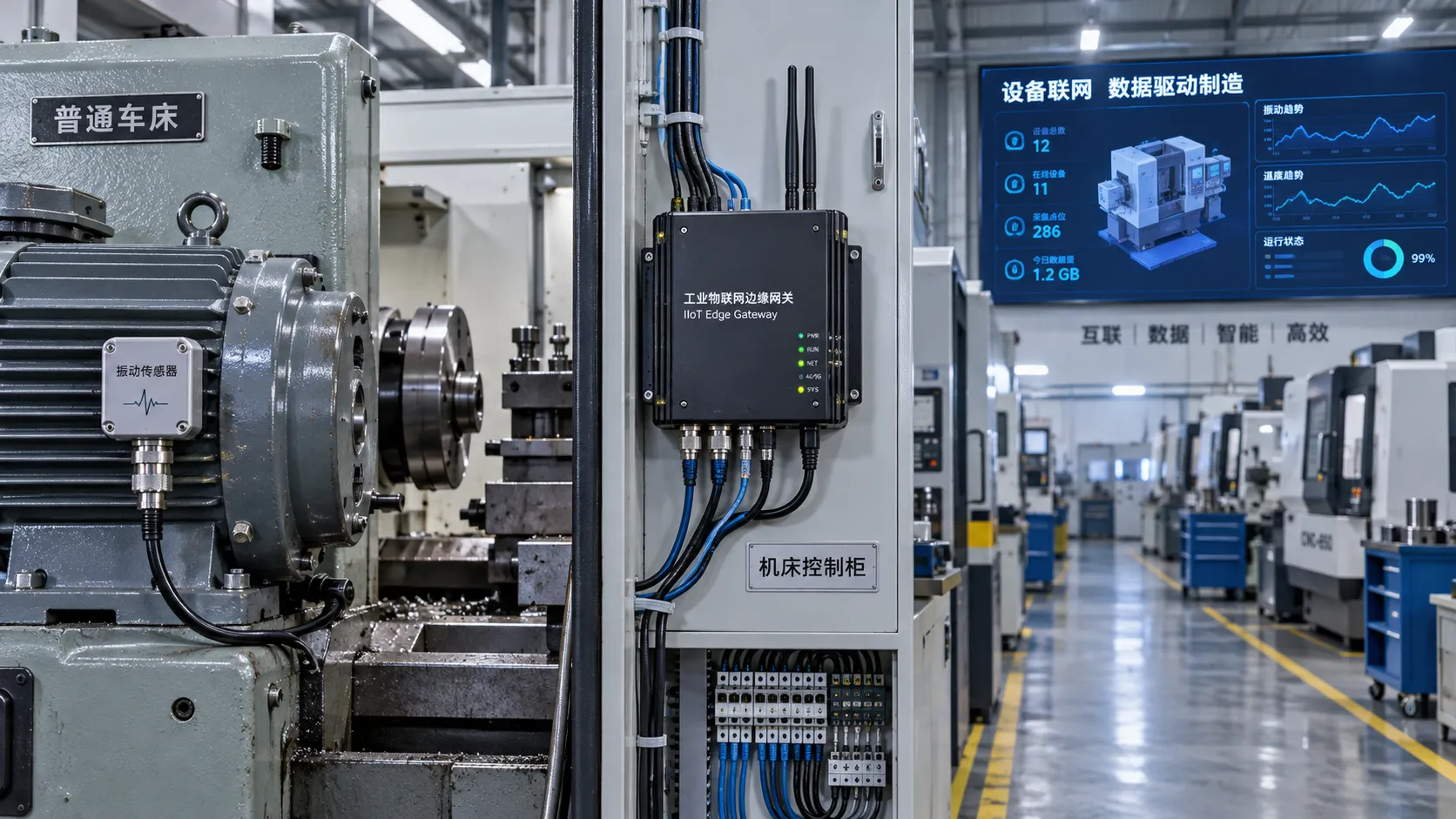
Choosing an Industrial IoT Platform: Key Criteria for Legacy Equipment
Choose an industrial IoT platform for legacy equipment with confidence. Discover key checks for connectivity, data integrity, security, and lifecycle costs before investing.
Related News
- 00
0000-00
Laser vs. Resistance Spot Welding: Which Fits Automotive Body Assembly? - 00
0000-00
How to Choose Welding Tools for Field Repair Work - 00
0000-00
What Welding Equipment Documents Should Suppliers Provide? - 00
0000-00
Welding Fume Extraction PPE: When Respirators Are Not Enough for Shop Safety - 00
0000-00
Which ANSI Standards Apply to Welding Equipment in Industrial Fabrication?
0000-00
Welding Metallurgy Expert
Weekly Insights
Stay ahead with our curated technology reports delivered every Monday.