
How to Compare Calibration Tools: Range, Uncertainty, and Traceability





Two calibration tools can look almost identical on a specification sheet and still support very different measurement decisions. One may cover the required range but lose useful performance near its endpoints. Another may offer excellent resolution while providing insufficient evidence of uncertainty or metrological traceability.
For technical evaluators, the question is not simply which instrument is “more accurate.” It is which tool can support a defensible acceptance decision under the conditions where it will actually be used. GPTWM’s product comparison resources for calibration tools focus on that distinction: connecting specifications, calibration evidence, and industrial operating requirements rather than ranking equipment by headline numbers.
A useful comparison begins with three linked questions: Does the tool cover the application? Is its measurement uncertainty sufficiently small? Can the resulting measurements be connected to an appropriate reference through documented calibration?
Define the measurement job before comparing instruments
“Calibration tool” can mean a pressure calibrator, electrical source, torque reference, temperature dry block, or dimensional standard. These devices have different operating principles, but the selection logic is similar. Start by defining the quantity being measured or generated, the required test points, and the acceptance limits.
That definition needs more detail than a maximum range. A torque reference for assembly-tool verification must suit the loading direction, fixtures, and loading sequence. A temperature system must account for probe immersion and temperature uniformity. An electrical calibrator must match the required signal type, load, frequency, and connection arrangement.
Before requesting quotations, document:
- Measurement requirements: quantity, units, operating range, test points, and tolerance limits.
- Use conditions: laboratory or production floor, temperature variation, vibration, contamination, and transport frequency.
- Decision requirements: the applicable procedure, uncertainty target, and rule for declaring conformity.
- Operational constraints: throughput, warm-up time, fixtures, software compatibility, and service availability.
This prevents a common procurement mistake: buying an instrument that satisfies the purchasing specification but cannot support the actual calibration method.
Range: compare usable coverage, not the largest number
A broad range is convenient, but coverage alone does not establish capability. Performance may depend on the selected subrange, the reading, the full-scale value, or a combination of these factors.
Read the specification mathematically
Consider a hypothetical pressure instrument specified at ±0.05% of full scale over a 100-bar range. That term corresponds to ±0.05 bar throughout the range. At a 5-bar test point, it represents 1% of the reading. A narrower-range instrument may therefore be better suited to low-pressure work, even if its headline percentage looks less impressive.
Specifications expressed as a percentage of reading plus a fixed term require similar care. Calculate the resulting limit at every critical test point. Do not compare “±0.02%” with “±0.05%” until the reference basis, additional terms, and operating conditions are aligned.
Also distinguish measurement range from generation capability. A pressure calibrator might measure the required pressure but need an external pump to generate it. An electrical source may cover the desired voltage yet fail to maintain that output under the connected load.
Look for gaps inside the range
Check range transitions, minimum usable outputs, overload limits, and any restrictions on continuous operation. For bidirectional torque or pressure work, confirm capability in both directions. For alternating electrical signals, verify frequency-dependent performance rather than relying on a DC specification.
The most useful comparison is a test-point map. List the points required by your procedures, then record each candidate’s applicable specification and operating restrictions. A single uncovered point can outweigh an otherwise attractive feature list.
Uncertainty: turn brochure claims into a measurement budget
Resolution, stated accuracy, and measurement uncertainty are not interchangeable. Resolution describes the smallest displayed or generated increment. A manufacturer’s accuracy specification generally defines performance limits under stated conditions. Measurement uncertainty characterizes the dispersion of values attributed to the measurand, using the available information.
A calibration certificate’s uncertainty describes the reported calibration result. It does not automatically describe your future measurements on the production floor.
Separate calibration uncertainty from uncertainty in use
An application uncertainty budget may need to account for the reference’s calibration uncertainty, drift since calibration, resolution, repeatability, environmental effects, and the calibration method. Connections, fixtures, and the behavior of the device under test can also matter.
Examples differ by discipline:
- Temperature: block stability, axial gradients, loading effects, probe immersion, and reference thermometer uncertainty.
- Torque: alignment, adapters, loading rate, repeatability, and mechanical interfaces.
- Pressure: leaks, pressure-head corrections, media compatibility, and stability during readings.
- Dimensional measurement: thermal expansion, contact force, alignment, and surface condition.
Build the budget around the measurement model, not a checklist of every published number. Avoid counting the same effect twice—for example, including a broad manufacturer limit and then separately adding contributions already covered by that limit without justification.
Where independent contributions are expressed as standard uncertainties, they are commonly combined by root-sum-of-squares. Correlations require additional treatment. Expanded uncertainty is then obtained using an appropriate coverage factor. A quoted value with k = 2 often corresponds to approximately 95% coverage, but the certificate’s stated basis should govern interpretation.
Use uncertainty ratios carefully
A test uncertainty ratio, or TUR, can provide a useful screening metric. Definitions should be stated explicitly because procedures and organizations may use different conventions.
For a symmetric tolerance, one common convention compares the tolerance half-width with expanded measurement uncertainty. If a hypothetical instrument has a tolerance of ±1.0 unit and the calibration process has expanded uncertainty of 0.25 unit, the resulting TUR is 4:1.
That ratio is not a universal pass condition. A customer specification, sector requirement, or internal risk policy may call for a different approach. More importantly, the denominator should represent the relevant calibration process uncertainty—not simply the reference instrument’s display resolution or best certificate value.
Acceptance decisions need a rule, not just a reading
Even a capable calibration system can produce ambiguous results near a tolerance boundary. Evaluators should therefore compare the decision rules supported by the procedure and software, not just the instruments.
Suppose an allowable error is ±1.0 unit. A measured error of +0.9 unit with expanded uncertainty of 0.3 unit lies within the nominal limit, but its uncertainty interval extends beyond it. Whether that result is declared conforming depends on the agreed decision rule.
One approach uses guard bands, reducing the acceptance zone to address the risk of accepting a nonconforming item. Other approaches allocate risk differently. Neither “the reading is inside tolerance” nor “the uncertainty interval crosses the limit” is a complete decision rule on its own.
Ask suppliers to demonstrate a near-limit result. Can the software apply your rule, distinguish measured error from uncertainty, and preserve the basis for the conformity statement? This small demonstration often reveals more than a polished dashboard.
Traceability: inspect the evidence behind the claim
Metrological traceability is a property of a measurement result: it can be related to a reference through a documented, unbroken chain of calibrations, each contributing to measurement uncertainty. A label stating “traceable” is not enough to establish that chain.
Similarly, traceability alone does not prove fitness for purpose. A result may be traceable yet have uncertainty too large for the intended tolerance.
What to request before purchase
Ask for a representative calibration certificate for the relevant instrument type and service level. Review the equipment identification, method, measurement results, units, calibration conditions, stated uncertainties, and traceability information. Confirm that the points and functions match the proposed application.
ISO/IEC 17025 accreditation provides useful evidence of laboratory competence, but the laboratory’s scope matters. Check that its accredited activities cover the relevant quantity, range, and capability. A laboratory’s best published calibration and measurement capability does not automatically equal the uncertainty it will report for your instrument.
For an adjustable instrument, clarify whether the service provides as-found results before adjustment and as-left results afterward. As-found information helps determine whether earlier measurements may require review. A certificate showing only post-adjustment performance leaves that question harder to answer.
Also confirm how out-of-tolerance findings are communicated and whether the certificate reports actual results rather than only a pass/fail statement. These details influence audit readiness and the practical value of the calibration service.
Build a comparison sheet that exposes trade-offs
A useful evaluation sheet separates mandatory capability from preferences. The following framework keeps attractive extras from masking a fundamental measurement gap.
Apply hard gates first. Missing a required range, lacking adequate uncertainty, or failing a traceability requirement should not be offset by a high score for connectivity or portability. Score convenience and lifecycle factors only after candidates pass those gates.
Check what happens after the first calibration
The lowest purchase price may not produce the lowest cost per defensible result. Include required accessories, calibration services, transport, spare equipment, operator training, and time spent entering or correcting records.
Calibration intervals deserve particular attention. A fixed annual interval may be convenient, but the appropriate interval depends on stability, usage, environmental exposure, consequences of failure, and applicable requirements. Review historical results and intermediate checks to support interval decisions rather than assuming every tool behaves alike.
For connected calibration systems, evaluate record integrity as carefully as data transfer. Confirm instrument identification, units, correction handling, uncertainty calculations, software version control, and export usability. Automated transcription reduces one source of error; an incorrect configuration can reproduce another at scale.
Where practical, run a trial using representative devices and normal operators. Include a low-range point, a near-limit result, and the least favorable expected environment. Observe setup time, stabilization, repeatability, and reporting—not just whether the instrument turns on and displays a plausible value.
Select the tool that makes the decision defensible
A strong calibration-tool recommendation should be explainable in a few sentences: the equipment covers the required test points; the application uncertainty supports the tolerance and decision rule; the calibration evidence establishes suitable traceability; and the organization can maintain that capability throughout use.
This is the perspective GPTWM brings to industrial metrology evaluation: specifications matter because of the manufacturing decisions they support. The best choice is not necessarily the widest-range, highest-resolution, or most connected instrument. It is the one whose results your team can use confidently—and explain when a result is challenged.
Related News
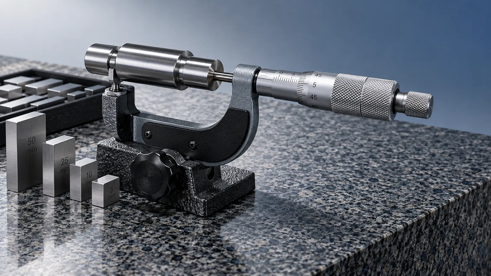
Choosing Industrial Metrology Tools: Matching Measurement Uncertainty to Tolerances
Improve industrial tool selection for metrology by matching measurement uncertainty to tolerances. Learn how to reduce inspection risk and choose equipment with confidence.
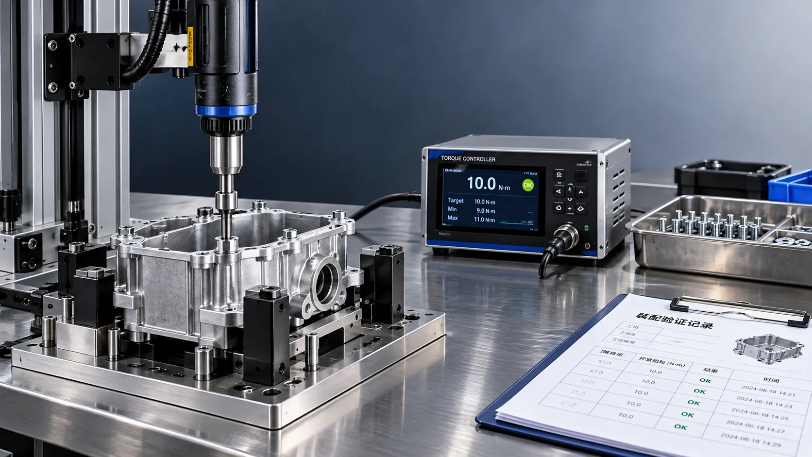
Torque System Suppliers: How to Assess References for Assembly Projects
Explore supplier and solution references torque systems buyers should verify. Assess assembly fit, traceability, and support to reduce risk and choose with confidence.

Equipment Application Guidance for the Middle East: Managing Heat and Dust
Explore application guidance Middle East teams can use to manage heat and dust, protect welding equipment, batteries and precision tools, and reduce downtime. Get practical tips.

Choosing a Handheld Laser Welding Supplier: Weld Trials, Training, and Service
Choose a handheld laser welding supplier with proven weld trials, safety training, and reliable service. Learn what to verify before buying to reduce downtime and protect your investment.

Choosing an Industrial IoT Platform: Key Criteria for Legacy Equipment
Choose an industrial IoT platform for legacy equipment with confidence. Discover key checks for connectivity, data integrity, security, and lifecycle costs before investing.

In-House vs. Outsourced Aircraft Maintenance: Comparing Total Costs
Compare aerospace maintenance cost for in-house vs. outsourced aircraft upkeep. Discover hidden expenses, downtime impacts, and break-even factors to find the best fit for your fleet.

How to Select High-Precision Measuring Instruments for Tight-Tolerance Production?
High-precision measuring instruments are essential for tight-tolerance production. Learn how to evaluate accuracy, repeatability, environment, calibration, and data integration.

How Industrial Innovation Supplier Networks Reduce Sourcing Risk for Manufacturers
industrial innovation supplier network insights help manufacturers reduce sourcing risk, control lifecycle costs, and choose reliable tools, services, and suppliers with confidence.

What Welding Equipment Documents Should Suppliers Provide?
What welding equipment documents should suppliers provide? Explore essential compliance, safety, test, traceability, warranty, and service records for confident sourcing.
Related News
- 00
0000-00
How to Compare Calibration Tools: Range, Uncertainty, and Traceability - 00
0000-00
Choosing Industrial Metrology Tools: Matching Measurement Uncertainty to Tolerances - 00
0000-00
How Often Should Precision Measuring Instruments Be Calibrated? - 00
0000-00
Which Precision Measuring Tools Are Best for Incoming Inspection? - 00
0000-00
Planning Access, Material Flow, and Clearance Around a 3200mm Sliding Saw
Metrology Fellow
Weekly Insights
Stay ahead with our curated technology reports delivered every Monday.