
How Energy-Efficient Welding Equipment Cuts Power Use in High-Volume Fabrication





Power use in a high-volume welding line is determined by far more than the nameplate rating of each machine. The meaningful figure is the energy required to produce an accepted joint, including arc time, idle time, wire feeding, fume extraction, cooling, part handling, and the electricity consumed when a weld must be repaired. Energy-efficient welding equipment reduces consumption by lowering conversion losses, shortening productive cycle time, and preventing unstable process conditions that turn electrical input into spatter, heat distortion, or rework.
That distinction matters because a lower-power source is not automatically the lower-energy choice. A unit operating near its efficient range with stable arc control can consume less energy per finished assembly than an undersized source driven at its thermal limit, repeatedly restarting, or producing inconsistent fusion. The useful comparison is therefore energy per accepted part, paired with arc-on time, reject rate, and throughput. Looking at only kWh on the facility meter can hide a process change that reduces welding energy while increasing repair activity elsewhere in the cell.
Start With the Energy Profile of the Welding Cell
High-volume fabrication often includes long stretches of non-arc time. Fixtures clamp and release, robotic axes reposition, components are indexed, wire is trimmed, gas pre-flow begins, and the power source remains energized while no metal is being joined. On lines with multiple stations, these gaps can add up to a substantial base load. A proper energy review separates three conditions: productive welding, ready-but-idle operation, and auxiliary load.
Productive welding energy is driven by voltage, current, travel speed, deposition efficiency, and the time needed to complete each weld. Ready-but-idle energy comes from energized power electronics, displays, feeders, coolant pumps, control cabinets, and connected automation. Auxiliary load includes extraction fans, compressed-air devices, chilled-water systems, positioners, and local lighting. Each category needs a different response. Reducing arc energy through better waveforms will not correct an oversized extraction fan that runs at full speed through every production pause.
Metering at the whole-building level is useful for cost accounting but rarely specific enough to guide equipment selection. Temporary submetering at the welding feeder, the fume-extraction branch, and the cooling circuit reveals whether the dominant loss is inside the welding process or around it. Production counts and accepted-part counts should be recorded over the same interval. Without that denominator, a change in shift volume or product mix can be mistaken for an efficiency gain.
Why Inverter Power Sources Change the Equation
Modern inverter welding power sources convert incoming electrical power at high frequency and regulate output electronically. Compared with older transformer-based equipment, this architecture generally reduces no-load consumption and provides faster control of the welding waveform. The operational value is not simply lower electrical draw. Faster response to arc-length changes can keep transfer behavior more stable, limiting excessive spatter and reducing the need for prolonged arc time to correct an uneven bead.
For gas metal arc welding, waveform control can tailor short-circuit behavior, pulse frequency, peak current, background current, and inductance. Those settings influence heat input and droplet transfer. A process tuned for a thin galvanized steel assembly requires a different balance from a heavy carbon-steel bracket. Applying a high-output procedure to thin material may create burn-through or distortion; reducing current without revising wire-feed speed, shielding gas, and travel motion can create lack of fusion. Both outcomes consume energy again during repair.
Inverter efficiency should still be evaluated under the intended duty pattern. Equipment advertised around peak output may spend most of a production shift at moderate current, cycling between short welds and handling pauses. The relevant questions are no-load draw, efficiency at common operating points, cooling behavior at the actual duty cycle, and whether standby features can be coordinated with the cell. A power-saving mode that wakes too slowly or disrupts automated sequencing can increase lost cycle time and encourage it to be bypassed.
Match the Process Window to the Part, Not the Highest Available Output
Energy saving begins with a qualified process window: the combination of material, joint geometry, wire or filler, shielding gas, power mode, travel speed, and fixture condition that repeatedly delivers the required weld. Once that window is stable, energy reduction comes from narrowing avoidable variation rather than indiscriminately lowering amperage.
Consider a repetitive fillet weld on carbon steel. If a conventional spray-transfer procedure deposits more weld metal than the joint requires, increasing travel speed or using a controlled pulsed mode may reduce heat input and arc time while maintaining fusion. The result depends on fit-up and access. A joint with variable root gap may need a more tolerant procedure, and forcing a faster program onto it can cause underfill or inconsistent penetration. The power reduction is then erased by grinding and rewelding.
Stainless steel and aluminum require further caution because heat management affects appearance, distortion, and metallurgical performance. Aluminum's high thermal conductivity can make a seemingly low-energy setting inadequate at the start of a weld or near a large heat sink. Stainless steel may show discoloration or distortion when heat accumulates across closely spaced welds. Sequencing, fixture design, and part temperature can be as important as source efficiency. An energy program that ignores those interactions can produce an attractive meter reading alongside higher scrap or finishing load.
Parameters That Should Be Evaluated Together
- Wire-feed speed and current: on many GMAW systems these are closely linked. Reducing one without confirming deposition and penetration can make a weld slower rather than more efficient.
- Voltage, arc length, and inductance: these settings affect arc stability and spatter. An arc that is too long wastes energy in excess heat and may widen the bead beyond what the joint needs.
- Travel speed and fixture repeatability: faster motion saves arc time only when torch-to-work distance, joint location, and clamping remain consistent from part to part.
- Pre-flow and post-flow gas timing: overly generous settings extend cycle time and consume shielding gas, yet aggressive reduction can contaminate starts, ends, and hot tungsten in TIG applications.
- Weld sequence: distributing heat around an assembly can reduce distortion and allow shorter, more controlled welds than a continuous sequence that requires later straightening.
Duty Cycle Is a Scheduling Issue as Well as an Equipment Rating
Duty cycle is often misread as an energy-efficiency specification. It indicates how long a power source can deliver a stated output within a reference period before cooling is required. It does not state how much electricity a completed part consumes. However, selecting equipment with an appropriate duty cycle prevents thermal interruptions, fan overuse, output derating, and unplanned source changes that interrupt production.
A source sized far above the actual load may carry unnecessary capital cost and auxiliary consumption, especially where cooling fans and pumps remain active continuously. A source sized too close to its limit can spend more time running cooling systems at high speed, or require reduced output that lengthens weld time. The practical target is equipment that handles the real weld schedule with enough thermal margin for expected variation, rather than a rating chosen solely from the highest current listed on a procedure.
Cell scheduling also affects power demand. When several large sources initiate high-current welds simultaneously, the peak load can rise sharply even if total daily welding energy remains unchanged. Staggering starts, coordinating positioner motion, and avoiding unnecessary simultaneous warm-up reduces instantaneous demand. This is especially relevant where electrical infrastructure is constrained or where a demand charge is tied to short peak intervals. The change must preserve takt time; a delayed weld that creates downstream starvation is not an efficiency improvement.
Intelligent Controls Reduce Invisible Consumption
Connected welding systems can log arc-on time, voltage, current, wire consumption, faults, and program selection at a level that exposes recurring waste. The most useful data is tied to a part family, station, and shift pattern. A rise in kWh per accepted part may indicate longer arc time, but it may also come from a torch liner beginning to drag wire, a worn contact tip creating unstable transfer, a fixture moving out of position, or a program being changed without matching the consumable setup.
Automatic power-down and sleep functions are valuable during planned breaks and extended interruptions. Their settings should follow the production rhythm. A short timeout may repeatedly cycle equipment during normal indexing, while a long timeout leaves a bank of sources energized through changeovers or maintenance windows. For robotic cells, the sequence should distinguish between a brief fault recovery and a confirmed inactive state. Powering down a source in the middle of diagnostic work can extend downtime and lead to uncontrolled restarts.
Program management is equally important. A locked, validated parameter set prevents gradual drift caused by ad hoc adjustment. The goal is not to eliminate all process changes; different material thicknesses, joint preparations, and part temperatures require legitimate variation. Controls should make those changes traceable and ensure that the selected program corresponds to the correct wire diameter, shielding gas, torch configuration, and fixture. An energy-efficient waveform used with the wrong consumable setup can increase spatter and contact-tip wear.
Peripheral Equipment Often Determines the Real Savings
Water-cooled torches, recirculating chillers, fume extractors, wire feeders, and compressed-air circuits can consume power for longer than the arc itself. A water-cooled setup may be essential for high-current, sustained welding, but running its pump continuously on a low-duty station can be disproportionate to the thermal load. Air-cooled torches can reduce auxiliary energy in suitable applications, though they may become uncomfortable or overheat during long, high-amperage welds. The choice should be based on actual thermal exposure, not a blanket preference for one torch type.
Fume extraction requires a similar balance. Excessive airflow may pull shielding gas away from the weld zone, leading to porosity and rework, while insufficient capture creates an unsafe and unstable working environment. Variable-speed extraction, properly positioned capture arms, clean filters, and interlocks linked to arc activity can reduce fan energy without weakening capture performance. The extraction system must be commissioned with the welding process active because a setting that looks acceptable when the arc is off can behave differently in the gas plume.
Compressed air deserves scrutiny where pneumatic clamps, blow-off nozzles, and wire-cleaning devices are used. Leaks, continuous blow-off, and high pressure settings create energy demand outside the welding source. Replacing a continuous air blast with a timed pulse, or repairing a leaking fixture circuit, often has a clearer payback than marginal changes to a stable weld program. These measures should not introduce chips or moisture into the joint area, where contamination would create a far more expensive quality problem.
Maintenance Protects Electrical Efficiency and Weld Quality
A stable arc uses less corrective energy than an arc fighting poor feeding or electrical resistance. Contact tips, liners, drive rolls, ground connections, torch cables, and work clamps should be inspected in relation to observed process behavior. Bird-nesting at the feeder, erratic current readings, changing arc sound, and rising spatter are not merely consumable issues; they often increase arc-on time and rework.
Grounding problems are frequently underestimated. A loose or contaminated work connection can cause unstable arc characteristics and local heating. Replacing a power source without correcting poor return paths leaves the underlying loss in place. Cable routing also matters: damaged insulation, undersized extensions, excessive cable length, and sharp bends add resistance or create intermittent faults. The remedy is not always a heavier cable; the required conductor and routing should match the source output, installation length, and movement pattern of the cell.
Cooling passages and fan intakes need attention in dusty fabrication areas. Restricted airflow raises internal temperature, which can increase fan duty, trigger thermal protection, and shorten component life. Cleaning should follow the equipment instructions and be planned around contamination risk. Blowing debris deeper into a power source or disturbing sensitive electronics creates a different reliability problem.
Evaluate Upgrades Through Accepted Output
An equipment upgrade should be tested against a representative production mix, including the joint types that cause the most variation. Record energy at the station, cycle time, arc-on time, downtime, wire use, shielding-gas use, rework, and inspection outcomes before and after the change. Separate setup periods from steady production. A new source can appear inefficient during training, fixture adjustment, or initial program qualification even when its stable-state performance is better.
Comparison should also account for the work moved elsewhere. A faster weld that creates more heat distortion may transfer cost to straightening. A lower-current program that needs an extra pass may reduce peak power but increase total electrical input. Conversely, a controlled waveform that uses slightly more instantaneous power can still reduce energy per part by completing the joint cleanly in less time and avoiding finishing work.
The strongest energy-saving results come from treating the welding source, process program, fixtures, consumables, and auxiliaries as one production system. When each element is matched to the actual joint and duty pattern, power use falls for a durable reason: fewer idle losses, less excess heat, fewer unstable welds, and less energy spent making the same part twice.
Related News
Selecting Adjustable Torque Tools for Repeatable Fastener Assembly
Adjustable torque tools: learn how to match range, accuracy, control methods, calibration, and ergonomics for repeatable, reliable fastener assembly.
How to Select Aerospace Inspection Tools for Aircraft Maintenance Tasks
Aerospace maintenance inspection tools: learn how to select reliable, traceable equipment for aircraft access, accuracy, calibration, and compliant maintenance decisions.
How to Select Wire Bonding Tools for Fine-Pitch Semiconductor Packaging
Explore semiconductor manufacturing tools for wire bonding and learn how to select precision solutions for fine-pitch packaging, reliable loops, accuracy, and yield.
How to Compare Industrial Tool Suppliers for Quality, Lead Time, and Total Cost
Industrial tool selection supplier comparison made simple: evaluate quality, lead times, total cost, service, and supply resilience for confident sourcing decisions.
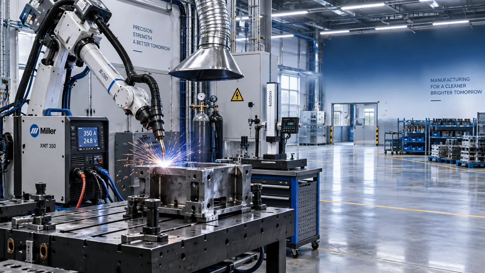
Industrial Equipment Application Guidance: Match Machines to Operating Conditions
Application guidance industrial equipment: match capacity, duty cycle, materials, site conditions, safety, and lifecycle cost to improve reliable output. Read the guide.
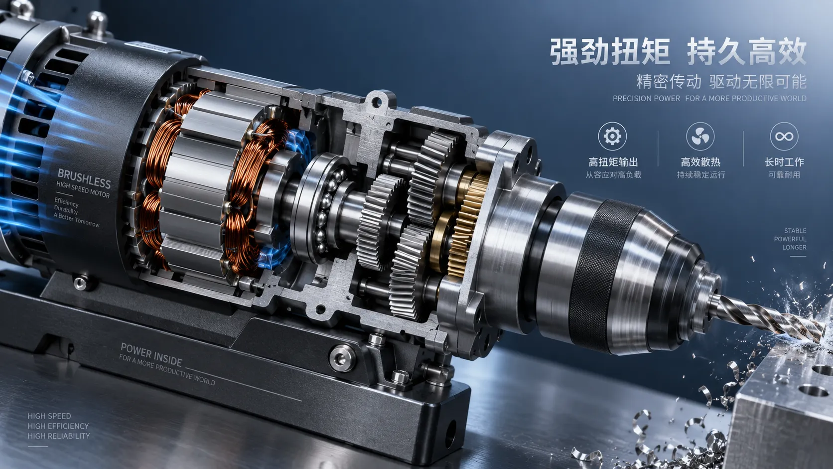
Selecting High-Speed Brushless Tool Motors for Torque, Heat, and Duty Cycle
High speed brushless tool motors: learn how to balance torque, heat, gearing, and duty cycle for reliable industrial tool performance and longer service life.
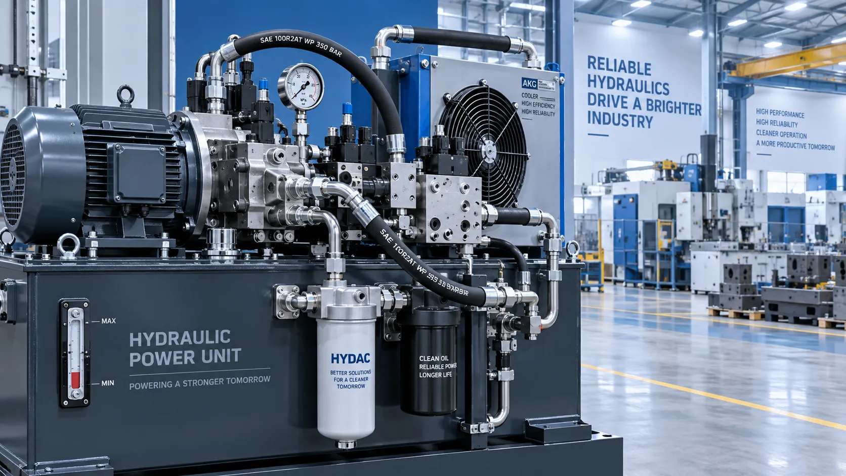
What Determines Industrial Hydraulic System Price for Heavy-Duty Equipment?
Industrial hydraulic system price depends on duty cycle, pressure, components, cooling, and integration. Compare quotes intelligently to secure reliable heavy-duty performance.
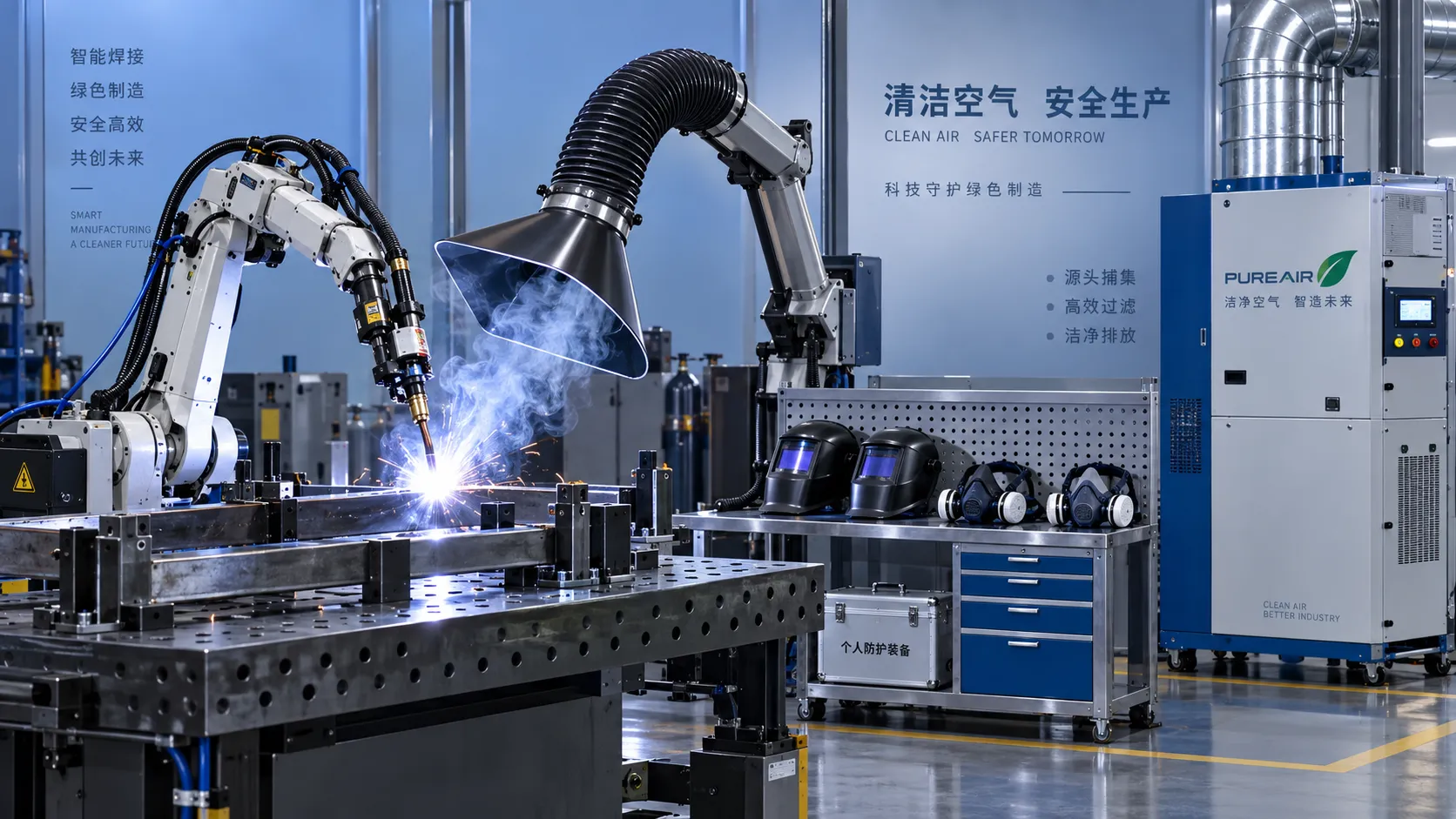
Welding Fume Extraction PPE: When Respirators Are Not Enough for Shop Safety
Welding fume extraction PPE: learn why respirators alone fall short and how source capture, ventilation, and layered controls improve shop safety.
How to Select Optical Metrology Solutions for Tight-Tolerance Manufacturing
Optical industrial metrology solutions for tight-tolerance manufacturing: evaluate accuracy, surface compatibility, workflow, and traceability to select with confidence.
Related News
- 00
0000-00
Welding Fume Extraction PPE: When Respirators Are Not Enough for Shop Safety - 00
0000-00
Which ANSI Standards Apply to Welding Equipment in Industrial Fabrication? - 00
0000-00
How Energy-Efficient Welding Equipment Cuts Power Use in High-Volume Fabrication - 00
0000-00
Which ISO Standards Govern Welding Technology Quality Control and Qualification? - 00
0000-00
North American Welding Innovations Reshaping Automation, Quality, and Labor Productivity
Welding Metallurgy Expert
Weekly Insights
Stay ahead with our curated technology reports delivered every Monday.