
How to Select Electronics Manufacturing Tools for Fast, Reliable PCB Prototyping





Start with the Prototype Decision You Need to Make
Fast PCB prototyping is often treated as a purchasing problem: compare soldering stations, pick a desktop pick-and-place machine, add an inspection camera, and start building. That approach works only for simple boards. Once prototypes involve fine-pitch packages, mixed assemblies, power electronics, RF sections, small production runs, or repeated design revisions, the tool choice begins to shape the quality of engineering decisions.
For technical evaluators, the most suitable electronics manufacturing tools for prototyping are rarely the tools with the highest headline specifications or the lowest purchase price. They are the tools that produce a usable, repeatable result at the speed required by the development cycle, while making defects visible early enough to correct them. A toolset should help the team answer practical questions: Did the board assemble as intended? Is a failure caused by the design, the component, or the assembly process? Can the same result be reproduced after the next layout revision?
That changes how equipment should be assessed. Instead of selecting individual machines in isolation, evaluate the prototype workflow from stencil application through soldering, inspection, rework, and electrical validation. The main risk is not simply slow assembly. It is mistaking process variation for a circuit problem and spending engineering time debugging the wrong cause.
Match Tool Capability to Board Complexity, Not to a Generic “Prototype” Label
“Prototype” can describe anything from a two-layer controller board assembled by hand to a dense multi-layer board with fine-pitch BGAs and controlled-impedance layouts. Those builds need very different equipment. The first selection task is to define the failure modes the toolset must prevent or expose.
A basic through-hole or coarse-pitch surface-mount board may be well served by a temperature-controlled soldering iron, hot-air rework station, magnification, bench power supply, and standard hand tools. In this setting, operator access and thermal control matter more than automation. A complex board with 0.4 mm-pitch components, QFNs with bottom-side terminations, BGAs, large thermal pads, or densely populated double-sided assemblies requires greater process control. Hand assembly may still be possible, but its limitations must be accepted before it becomes the default method.
Assess the board against a short list of conditions before comparing equipment:
- Smallest component package and lead pitch.
- Presence of hidden solder joints, including BGAs, QFNs, LGA packages, and bottom-terminated power devices.
- Thermal mass variation across the board, especially large ground planes, shields, connectors, and metal-backed components.
- Need for double-sided reflow or mixed surface-mount and through-hole assembly.
- Expected number of design iterations and boards per revision.
- Whether the prototype is only for functional proof, or also for reliability, firmware validation, compliance preparation, or customer demonstration.
The distinction between functional proof and engineering validation deserves attention. A manually assembled board that powers up once may be enough to evaluate an early circuit idea. It is a weak basis for judging yield, thermal behavior, signal integrity, or field reliability. When prototypes are expected to inform production design choices, repeatable assembly conditions become more important than the fastest possible first build.
Evaluate the Assembly Chain, Not Just the Reflow Oven
Reflow equipment often receives most of the attention because it appears to be the center of PCB assembly. In practice, a reflow oven cannot compensate for inconsistent solder paste deposition, inaccurate placement, poor board support, or unsuitable thermal profiling. The bottleneck may sit upstream.
For manually placed boards, stencil printing is one of the highest-leverage steps to improve. A properly designed stencil, reliable board alignment, and controlled paste application reduce solder volume variation before the board enters the oven. This is especially relevant for fine-pitch components, exposed thermal pads, and devices with large numbers of small passive components. A basic fixture can be sufficient for low-volume use, provided it holds the PCB and stencil consistently and allows repeatable paste release.
When comparing desktop stencil printers or manual printing fixtures, technical teams should look beyond whether a board “fits.” Alignment repeatability, support for thin or flexible PCBs, ease of cleaning, stencil frame compatibility, and board changeover time all affect practical use. A setup that requires extensive adjustment for every board revision may be tolerable for one-off boards, but it becomes a drag when engineering releases frequent layout updates.
Placement equipment should be chosen according to component mix and revision volume. A manual vacuum pickup and placement aid can be effective for low counts and large packages. It loses efficiency when boards contain many 0402 or 0201 passives, multiple fine-pitch ICs, or repeated component rotations. Desktop pick-and-place systems can shorten placement time, but their real value lies in controlled positioning and reusable placement data. That value depends on the quality of component libraries, feeder setup, fiducial recognition, and verification of polarity and rotation data.
Before investing in automated placement, ask whether the team has the discipline to maintain machine-ready data. A pick-and-place machine fed by incomplete centroid files, inconsistent footprint origins, and unverified component rotations can create defects faster than manual placement. If each design is unique and board quantities are very low, outsourced assembly or a disciplined manual workflow may remain more efficient. If revisions are frequent and component populations are moderately dense, the ability to reuse validated setup data can justify automation quickly.
Thermal Control Matters More Than Oven Size
A prototype reflow oven should be evaluated by its ability to deliver an appropriate, repeatable thermal profile across the actual board, not by chamber dimensions alone. Boards with heavy copper, large connectors, shield cans, and power devices heat differently from sparse control boards. A profile that works on one layout may underheat solder joints on another or expose sensitive components to unnecessary thermal stress.
Useful evaluation questions include whether the oven supports programmable profiles, whether temperature measurement can be correlated with board-level thermocouple readings, how evenly it heats across the working area, and how consistently it performs over repeated cycles. A profile-capable oven without a practical way to measure the board itself still leaves the team relying on assumptions.
Convection reflow is generally more controllable than improvised hot-plate or radiant heating methods for assemblies with mixed thermal mass. Hot plates and localized heating tools retain a place in early experiments, package replacement, and very small boards. Their limitations become clear when results need to be compared across revisions or shared among several engineers. The issue is not that a simple tool cannot form a joint; it is whether the process can produce enough consistency to separate design faults from assembly defects.
Inspection Capability Should Reflect What the Team Cannot See
Inspection is often underfunded because it does not appear to add a manufacturing step. In prototype work, it may save more time than a faster placement machine. Every hidden or ambiguous defect that reaches electrical debug can consume hours of engineering effort.
At a minimum, the bench should support clear inspection of solder fillets, component markings, polarity indicators, bridges, paste residues, and damaged pads. A stereo microscope or high-quality digital inspection system is far more useful than casual magnification when working with fine-pitch components. The choice depends on the task. Stereo viewing provides depth perception and is often better for hand soldering and rework. Digital systems can support image capture, remote review, and documentation, but latency and limited depth perception can make delicate manual work harder.
For hidden-joint packages, visual inspection has an obvious boundary. An apparently clean BGA perimeter does not confirm ball collapse, joint integrity, or the absence of voiding beneath the package. Technical evaluators should decide early whether these packages belong in the prototype phase and, if so, how joint quality will be verified. The answer may involve X-ray access through an external service rather than purchasing in-house equipment. For many teams, occasional outsourced X-ray inspection is more rational than owning a system whose maintenance, safety requirements, and utilization cannot be justified.
Inspection also needs to be linked to action. A camera that identifies a bridge is useful only if the team can remove the bridge without damaging pads or neighboring components. This is why inspection and rework should be evaluated as a pair.
Choose Rework Tools for Controlled Removal, Not Just Solder Melting
Prototype rework is where inexpensive tools frequently reveal their limits. Removing a component is easy when the board is expendable. Removing it while preserving pads, nearby components, laminate integrity, and the option to assemble a replacement is the relevant capability.
A competent rework station should provide stable temperature control, controllable airflow, suitable nozzles, and a practical way to support the board. For larger boards or high-thermal-mass assemblies, bottom-side preheating can reduce the top-side temperature and airflow needed to reflow a joint. This lowers the chance of warped boards, lifted pads, disturbed adjacent components, and thermal damage to sensitive parts.
Fine-pitch and bottom-terminated packages may require more than generic hot air. Package-specific nozzles, controlled preheating, component lifting tools, flux management, solder wick, and reliable pad-cleaning methods are part of the process. The selected equipment should support the components the team expects to replace, not only the components it expects to assemble successfully.
Rework performance also depends on consumables. Incompatible flux residues, poor-quality solder wick, unsuitable tip geometries, or inconsistent solder paste can undermine a well-specified station. A realistic tool evaluation includes the availability of compatible consumables and replacement parts, particularly when equipment will be used across multiple labs or sites.
Measure Repeatability Through a Representative Build
Specification sheets are useful for screening options, but a representative build is the strongest evaluation method. Select a board or test coupon that resembles the intended prototype mix: small passive components, a fine-pitch IC, a thermal-pad device, connectors, and at least one component with significant thermal mass. Run enough boards to observe whether the same setup yields the same outcome.
The evaluation should record more than pass or fail. Track setup time, stencil alignment effort, placement corrections, reflow profile adjustments, visual defects, rework frequency, time to repair, and the number of defects that were discovered only during electrical test. This creates a practical picture of tool suitability.
This kind of trial often exposes an uncomfortable but valuable result: the most expensive machine is not necessarily the limiting factor. A team may discover that better board support, a more repeatable stencil process, improved microscope access, and documented profiles resolve more prototype defects than a larger automation purchase.
Plan for the Handoff to Production Without Buying a Production Line
Prototype equipment should support a credible transition to contract manufacturing or in-house volume assembly, but that does not require duplicating a production line in the lab. The more important objective is process visibility. Prototype boards should use controlled BOMs, clear assembly drawings, verified polarity conventions, documented stencil thickness, defined solder paste, and recorded reflow conditions. Those records help distinguish a design issue from a process issue when the board is transferred.
There is a practical limit to how closely a lab process can mirror production. Production equipment may use different printers, ovens, inspection systems, solder alloys, and panel handling methods. The prototype toolset should therefore be used to reveal sensitivity: whether the assembly only works under a narrow, improvised condition, or whether it has enough margin to tolerate normal process variation.
The best selection decision is often a balanced one. Invest in repeatable paste application, thermal profiling, usable inspection, and controlled rework before pursuing automation for its own sake. Add placement automation when component density and iteration frequency make manual work a recurring constraint. Use external services for specialized inspection or assembly steps until demand and utilization support ownership. A prototype lab built around visible, measurable, repeatable processes gives engineering teams faster answers and produces boards that are more trustworthy when the design moves beyond the bench.
Related News
Selecting Adjustable Torque Tools for Repeatable Fastener Assembly
Adjustable torque tools: learn how to match range, accuracy, control methods, calibration, and ergonomics for repeatable, reliable fastener assembly.
How to Select Aerospace Inspection Tools for Aircraft Maintenance Tasks
Aerospace maintenance inspection tools: learn how to select reliable, traceable equipment for aircraft access, accuracy, calibration, and compliant maintenance decisions.
How to Select Wire Bonding Tools for Fine-Pitch Semiconductor Packaging
Explore semiconductor manufacturing tools for wire bonding and learn how to select precision solutions for fine-pitch packaging, reliable loops, accuracy, and yield.
How to Compare Industrial Tool Suppliers for Quality, Lead Time, and Total Cost
Industrial tool selection supplier comparison made simple: evaluate quality, lead times, total cost, service, and supply resilience for confident sourcing decisions.
Industrial Equipment Application Guidance: Match Machines to Operating Conditions
Application guidance industrial equipment: match capacity, duty cycle, materials, site conditions, safety, and lifecycle cost to improve reliable output. Read the guide.
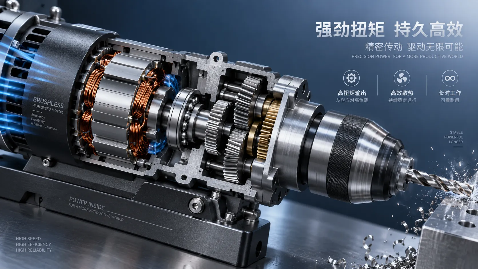
Selecting High-Speed Brushless Tool Motors for Torque, Heat, and Duty Cycle
High speed brushless tool motors: learn how to balance torque, heat, gearing, and duty cycle for reliable industrial tool performance and longer service life.
What Determines Industrial Hydraulic System Price for Heavy-Duty Equipment?
Industrial hydraulic system price depends on duty cycle, pressure, components, cooling, and integration. Compare quotes intelligently to secure reliable heavy-duty performance.
Welding Fume Extraction PPE: When Respirators Are Not Enough for Shop Safety
Welding fume extraction PPE: learn why respirators alone fall short and how source capture, ventilation, and layered controls improve shop safety.
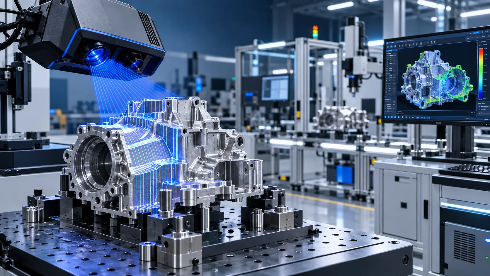
How to Select Optical Metrology Solutions for Tight-Tolerance Manufacturing
Optical industrial metrology solutions for tight-tolerance manufacturing: evaluate accuracy, surface compatibility, workflow, and traceability to select with confidence.
Related News
- 00
0000-00
Selecting Adjustable Torque Tools for Repeatable Fastener Assembly - 00
0000-00
How to Select Aerospace Inspection Tools for Aircraft Maintenance Tasks - 00
0000-00
How to Select Wire Bonding Tools for Fine-Pitch Semiconductor Packaging - 00
0000-00
Industrial Equipment Application Guidance: Match Machines to Operating Conditions - 00
0000-00
Selecting High-Speed Brushless Tool Motors for Torque, Heat, and Duty Cycle
Prof. Marcus Chen
Weekly Insights
Stay ahead with our curated technology reports delivered every Monday.