
How to Specify Torque Control Systems With Data Logging for Traceable Assembly





A fastening station can appear to be under control because the tool reaches the programmed torque value. The problem often becomes visible later: a quality investigation cannot determine which fastener was tightened, whether the joint was seated correctly, whether the operator received a pass result, or whether the tool was within calibration at the time. A stored final torque number alone rarely answers those questions.
To specify torque control systems with data logging for traceable assembly, start with the joint and the traceability decision—not with tool torque range or dashboard features. The selected system should control the complete fastening cycle, capture the evidence needed to verify it, reliably associate that evidence with the correct unit or assembly, and preserve records in a form that can be retrieved during a production or quality review. The right specification is therefore a combination of fastening performance, event data, identification logic, network architecture, and data-governance requirements.
Define what must be proven after the fastening event
Traceability has different meanings across assembly environments. On a low-risk internal assembly, it may be sufficient to record a pass/fail result and a final torque value against a work-order number. In a safety-critical, regulated, warranty-sensitive, or high-cost assembly, the record may need to show the complete torque-angle signature, tool serial number, controller program, operator or station identity, timestamps, calibration status, rework activity, and the serial number of the finished unit.
Write the required evidence before comparing controllers. Ask a practical question: when a specific unit is questioned months after shipment, what information must be available to reconstruct the fastening decision? The answer determines both the data fields and the integration effort.
- Fastener result: target, actual torque, torque limits, angle limits, cycle status, and fault reason.
- Curve evidence: torque versus angle, torque versus time, or both, where joint behavior must be examined rather than merely accepted or rejected.
- Unit association: product serial number, carrier ID, VIN-like identifier, batch number, or another controlled identifier.
- Process context: station, tool, controller, spindle, program version, fastening sequence, date and time, and user identity where applicable.
- Configuration history: parameter changes, authorization records, calibration events, repairs, and software or firmware revisions where these can affect process validity.
A system that logs abundant data but cannot link it consistently to the unit being built does not create useful traceability. Equally, a correctly scanned serial number has limited value if the fastening result is recorded only as a generic “OK” without the measurement information needed for review.
Match the control method to the joint, not simply the target torque
A stated torque target is not a complete tightening strategy. Friction at threads and under the fastener head can consume much of the applied torque, while clamp load—the condition usually being protected—may vary. Joint stiffness, fastener coating, lubrication, washers, prevailing torque, seating behavior, and component stack-up all influence the tightening signature. The system needs a control method that suits those realities.
For traceable assembly, specify whether the controller must retain the full curve for every cycle, only failed cycles, or selected sample cycles. Storing every high-resolution curve can create substantial data volume and network load. Sampling only pass/fail values reduces storage but weakens later analysis. The appropriate choice depends on the risk of the joint and the likely need to distinguish a true assembly defect from a tool, component, or process issue.
Also distinguish free-running tool capability from process capability at the joint. A tool may cover the required torque range, yet deliver poor repeatability if it operates near the low end of its range, if the reaction arrangement is unstable, or if the mechanical interface flexes. The specification should state the operating torque band, expected production duty cycle, required measurement accuracy, and the acceptable response when a target is not reached.
Make the fastening sequence enforceable
Traceable data is most credible when the system also prevents an incorrect sequence from being treated as a completed build. This matters where several fasteners must be tightened in a pattern, where distinct torque programs are used on one product, or where a manual operation can be performed out of order.
Consider a station assembling a housing with multiple perimeter fasteners and a central fastener requiring a different strategy. If the controller simply records independent tool cycles, it may store valid-looking results even though the central fastener was tightened before the housing seated. A sequence-capable system can require the correct program, confirm each position, prevent release to the next operation until the required cycle passes, and flag rework distinctly from initial assembly.
The necessary level of enforcement varies. Some applications only require program selection by barcode. Others need socket selection, tool positioning, vision confirmation, fixture interlocks, or programmable logic controller handshakes. Avoid specifying more automation than the station can maintain, but do not assume operator selection is adequate where a wrong program could produce an indistinguishable pass result.
Specify the failure states, not only the normal cycle
During evaluation, review what the system does when a fastener cross-threads, a socket slips, an operator releases the trigger early, a required part is missing, the tool disconnects, or a network connection drops. A traceability system should create a clear, time-stamped event for abnormal outcomes and should not silently overwrite or merge failed attempts into a later successful attempt.
Define whether a failed result locks the station, requires supervisor authorization, permits a controlled retry, or sends the assembly to a rework route. Rework needs its own logic. The record should make it possible to see that a fastening event was repeated, why it was repeated, and which result was ultimately accepted. Deleting failed cycles may make reports appear cleaner, but it weakens the process history precisely when an investigation is needed.
Choose identification architecture before choosing interfaces
The most frequent traceability gap is not missing torque data; it is an unreliable relationship between the data and the physical product. A scanner may capture a serial number at the beginning of a shift, while several units later pass through the same station. A workstation may accept manual entry, allowing an operator to proceed with an incomplete or incorrect identifier. These weaknesses cannot be repaired by adding more controller storage.
Map how a unit arrives, how its identity is read, where it is retained, and when it is released. The system should define a positive association between the active build and every fastening event. Depending on the production flow, that may involve a barcode or RFID reader, a fixture-carrier identifier, an MES transaction, a PLC-controlled pallet state, or a combination of these.
Evaluate the following details early:
- Whether the identifier format is validated against the scheduled product or allowed program.
- Whether duplicate, unreadable, or manually entered identifiers are blocked, flagged, or permitted under controlled exception handling.
- Whether one unit can contain multiple subassemblies with separate traceability records.
- Whether a unit can be removed mid-cycle and later returned without mixing its records with another unit.
- Whether station bypass, offline operation, and rework retain the required identity chain.
Where a line includes several controllers, do not rely on clocks that drift independently. Time synchronization and a consistent time-zone policy are basic requirements for reconstructing event order. The data model should also distinguish the time a fastening occurred from the time a record was transmitted to a higher-level system.
Assess data logging as an evidence system
Data logging must be evaluated for integrity, availability, and retrieval—not just capacity. Local controller memory may protect against a short network interruption, but it is not necessarily a long-term archive. A central database may simplify reporting, but it introduces dependency on network availability and interface reliability. Many practical installations use local buffering with controlled synchronization to a central repository.
Request clarity on record ownership and retention. Determine where raw curves, summarized results, parameter sets, audit events, and calibration records reside; who can modify them; and how records are exported for review. A CSV export may be adequate for limited analysis, while a structured database interface may be necessary where results must be linked automatically to manufacturing execution, quality, or enterprise systems.
Data integrity requirements should be proportionate to risk, but several questions are broadly useful. Can users alter a completed result? Are parameter changes logged with user identity and timestamps? Is a revised tightening program assigned a distinct version? Can records be backed up and restored without losing their linkage to original units? Is communication encrypted or segregated according to site policy? A controller that records values accurately but permits uncontrolled configuration changes leaves an avoidable gap in traceability.
Plan for network loss and recovery
Production networks are not always continuously available. Specify how many cycles the controller can buffer locally, whether the station can continue operating during a communication outage, and how it prevents duplicate uploads when the connection returns. The recovery process should be visible: records awaiting transfer, records transferred successfully, and records requiring intervention should not be indistinguishable.
There is a trade-off. Allowing unrestricted offline production maintains throughput but can permit units to advance before their records reach the central system. Blocking production immediately on a lost connection improves central control but may create unnecessary downtime for a brief interruption. The appropriate behavior should be defined by the assembly risk, downstream controls, and the organization’s ability to quarantine units when data synchronization is incomplete.
Check the physical tool and station conditions that affect the record
A high-quality digital record cannot compensate for a poor physical tightening setup. The evaluation should include tool ergonomics, cable or wireless coverage, battery strategy where relevant, reaction arms, sockets, extensions, fixturing, access angle, and operator reach. Side loading, worn sockets, unsupported extensions, or shifting reaction points can affect both delivered torque and curve shape.
Consider how the system identifies the actual tool used. In multi-tool cells, the controller should not accept a result from the wrong spindle merely because it received a valid cycle. Tool serial number, channel assignment, and program authorization help preserve that distinction. If interchangeable tools are expected, define the commissioning and verification procedure after replacement.
Calibration and verification also need to sit within the traceability model. A calibration certificate stored elsewhere may satisfy an administrative requirement, but production evidence is stronger when the system can alert users to overdue calibration, retain the applicable status, and prevent unauthorized use where necessary. Daily or periodic verification practices should be based on the joint’s criticality and the site’s quality system, rather than treated as a substitute for sound tool selection.
Turn the specification into acceptance tests
Before purchase approval, convert key requirements into demonstrations that a supplier or integrator can perform. Generic statements such as “supports Industry 4.0,” “offers traceability,” or “connects to MES” are not acceptance criteria. The demonstration should use representative workpieces or a controlled joint simulator, the intended identification flow, and sample error conditions.
- Run a valid fastening cycle and retrieve the result using the unit identifier.
- Show the stored fields, including the program version, tool identity, timestamp, measured values, and curve where required.
- Introduce a controlled failure such as an angle violation or interrupted cycle, then verify that it is retained and correctly associated with the unit.
- Attempt an incorrect sequence, wrong program, or mismatched identifier and confirm the defined prevention or escalation behavior.
- Disconnect the higher-level network, perform the agreed number of cycles, restore connectivity, and verify orderly synchronization without loss or duplication.
- Change an authorized parameter in a test environment and confirm the audit trail records who changed it, what changed, and when it became active.
These tests expose gaps that feature lists often conceal. They also force early agreement between manufacturing, quality, IT, maintenance, and automation teams. A torque controller may technically support a protocol, for example, while the required unit identifier, transaction timing, error response, and ownership of failed records remain unresolved.
Build a specification that can survive production reality
The strongest specification separates mandatory controls from preferences. Mandatory items usually include the required tightening strategy, operating range, measurement performance, unit association method, minimum data fields, retention location, outage behavior, access control, audit trail, and acceptance tests. Preferences may include screen layout, reporting style, wireless versus cabled operation, or a particular visualization format.
Do not request full curve storage merely because it is available, or a complex integration merely because a controller offers multiple protocols. Request them when they resolve a defined verification need. Conversely, do not reduce the requirement to a final torque value when the joint, sequence, or quality risk requires evidence of how that value was achieved.
Traceable assembly depends on a chain: the correct part is identified, the correct program is selected, the tightening event is controlled, the result is retained, exceptions remain visible, and the record can be retrieved later. Torque control systems with data logging should be selected against the weakest link in that chain. That approach produces a system that is useful not only when every cycle passes, but also when a real assembly question has to be answered.
Related News
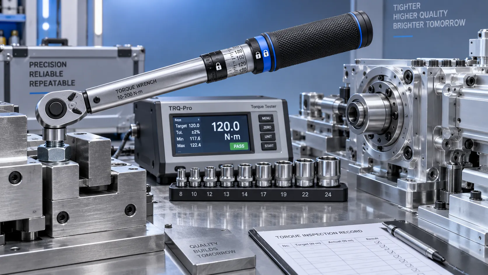
Selecting Adjustable Torque Tools for Repeatable Fastener Assembly
Adjustable torque tools: learn how to match range, accuracy, control methods, calibration, and ergonomics for repeatable, reliable fastener assembly.
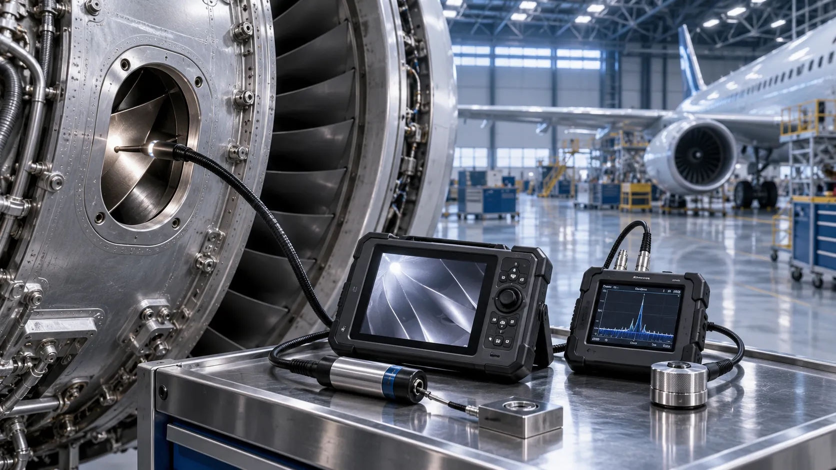
How to Select Aerospace Inspection Tools for Aircraft Maintenance Tasks
Aerospace maintenance inspection tools: learn how to select reliable, traceable equipment for aircraft access, accuracy, calibration, and compliant maintenance decisions.

How to Select Wire Bonding Tools for Fine-Pitch Semiconductor Packaging
Explore semiconductor manufacturing tools for wire bonding and learn how to select precision solutions for fine-pitch packaging, reliable loops, accuracy, and yield.
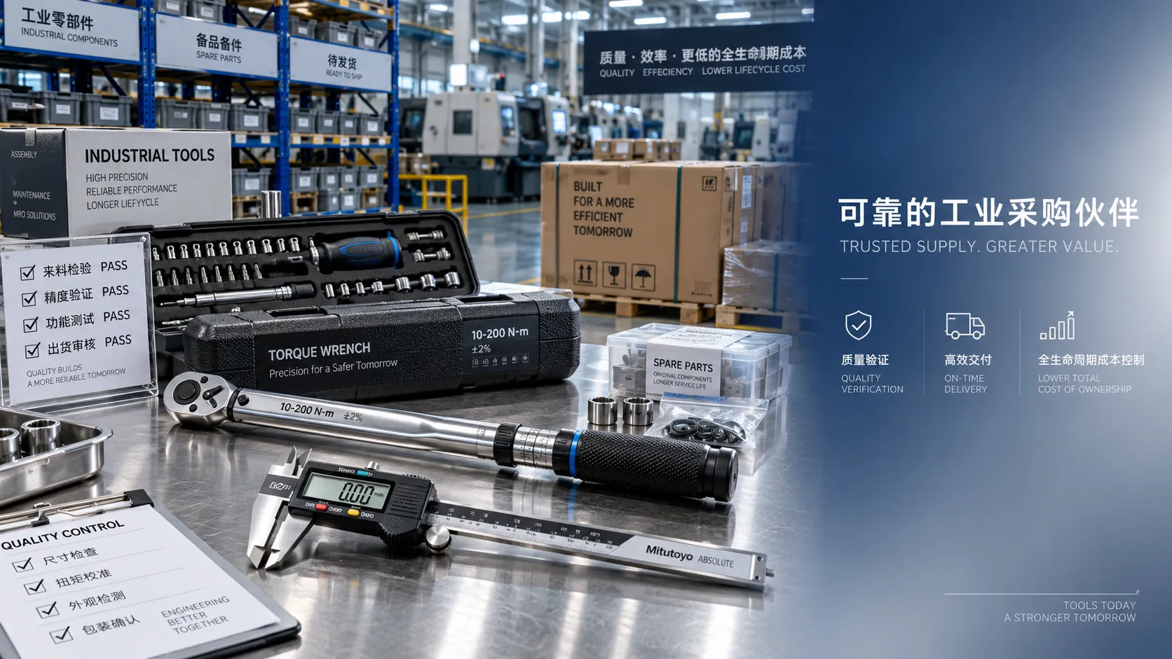
How to Compare Industrial Tool Suppliers for Quality, Lead Time, and Total Cost
Industrial tool selection supplier comparison made simple: evaluate quality, lead times, total cost, service, and supply resilience for confident sourcing decisions.

Industrial Equipment Application Guidance: Match Machines to Operating Conditions
Application guidance industrial equipment: match capacity, duty cycle, materials, site conditions, safety, and lifecycle cost to improve reliable output. Read the guide.
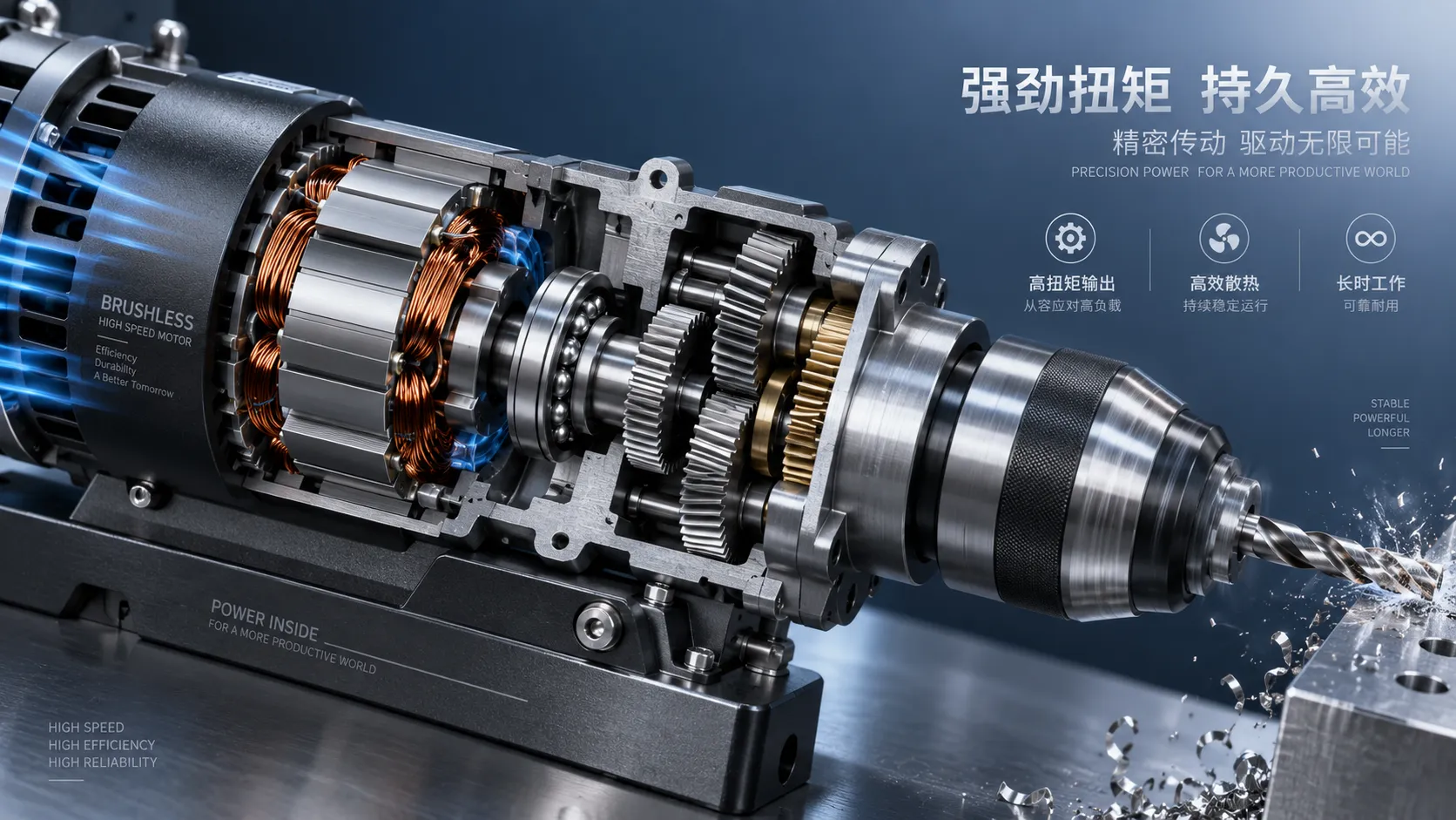
Selecting High-Speed Brushless Tool Motors for Torque, Heat, and Duty Cycle
High speed brushless tool motors: learn how to balance torque, heat, gearing, and duty cycle for reliable industrial tool performance and longer service life.
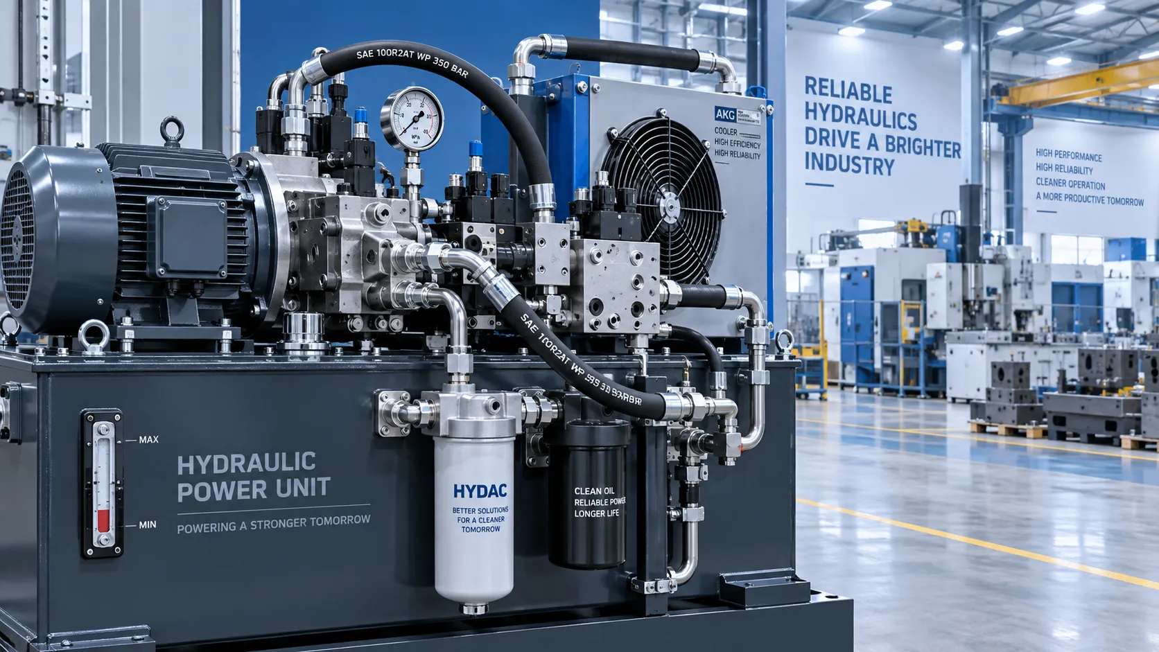
What Determines Industrial Hydraulic System Price for Heavy-Duty Equipment?
Industrial hydraulic system price depends on duty cycle, pressure, components, cooling, and integration. Compare quotes intelligently to secure reliable heavy-duty performance.
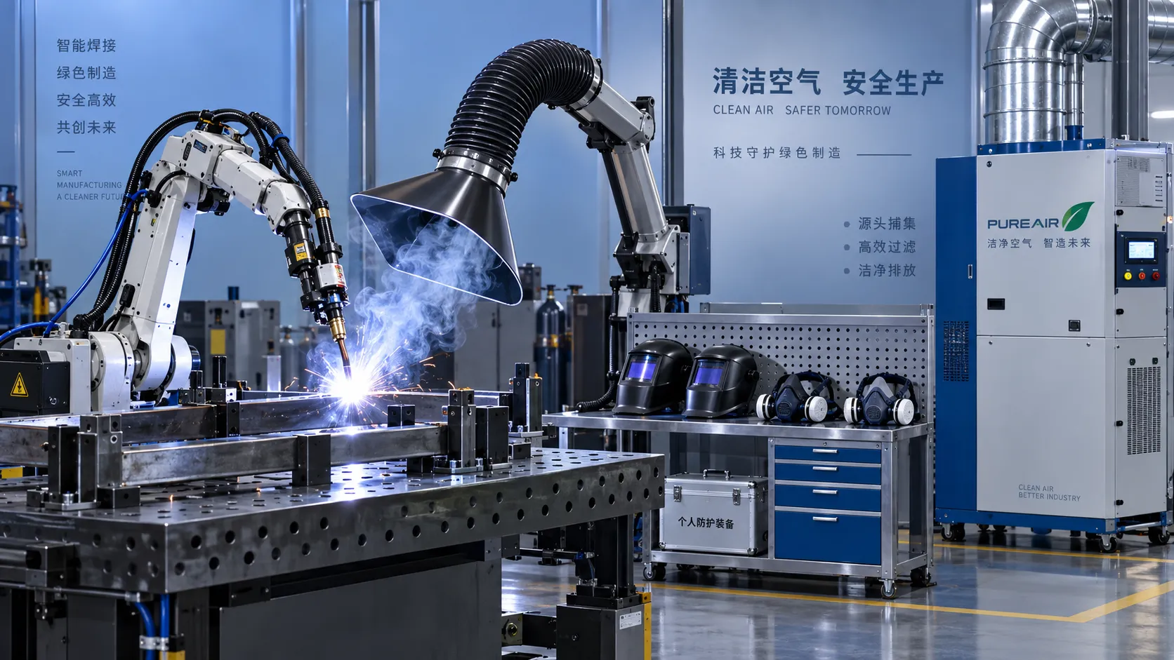
Welding Fume Extraction PPE: When Respirators Are Not Enough for Shop Safety
Welding fume extraction PPE: learn why respirators alone fall short and how source capture, ventilation, and layered controls improve shop safety.

How to Select Optical Metrology Solutions for Tight-Tolerance Manufacturing
Optical industrial metrology solutions for tight-tolerance manufacturing: evaluate accuracy, surface compatibility, workflow, and traceability to select with confidence.
Related News
- 00
0000-00
Selecting Adjustable Torque Tools for Repeatable Fastener Assembly - 00
0000-00
How to Select Aerospace Inspection Tools for Aircraft Maintenance Tasks - 00
0000-00
How to Select Wire Bonding Tools for Fine-Pitch Semiconductor Packaging - 00
0000-00
Industrial Equipment Application Guidance: Match Machines to Operating Conditions - 00
0000-00
Selecting High-Speed Brushless Tool Motors for Torque, Heat, and Duty Cycle
Prof. Marcus Chen
Weekly Insights
Stay ahead with our curated technology reports delivered every Monday.