
Precision Positioning in Electronics Manufacturing: A Practical Route to Higher Yield





Precision Positioning in Electronics Manufacturing: A Practical Route to Higher Yield
In electronics manufacturing, yield is often decided long before a board reaches final test. A placement offset that appears minor, a fixture that does not locate consistently, or a vision system referenced to the wrong datum can create defects that emerge later as solder bridges, insufficient joints, connector misalignment, or intermittent functional failures. These are rarely isolated quality events. They consume inspection capacity, complicate root-cause analysis, and make output less predictable.
That is why electronics manufacturing yield and precision positioning should be treated as one operational subject. Positioning is not merely the job of a pick-and-place machine. It is the controlled relationship between the PCB, the component, the fixture, the tool, the camera, and the measurement reference throughout assembly. When that relationship changes from station to station, even capable equipment can produce unstable results.
For project leaders, the practical question is not whether greater precision sounds desirable. It is where positional variation is entering the process, whether it is material to the product’s risk profile, and which corrective action will improve yield without creating an unnecessarily complex production line.
Positioning Errors Travel Through the Process
A board may be accurately registered at solder paste printing but poorly supported during placement. A component may be correctly placed yet shift during reflow because pad geometry, paste volume, package warpage, and thermal behavior interact. A finished assembly may then be inspected against a reference that does not match the production datum. Each stage can appear acceptable in isolation while the accumulated error reduces first-pass yield.
This matters more as assemblies become denser. Fine-pitch devices, bottom-terminated components, high-pin-count connectors, rigid-flex boards, and assemblies that combine surface-mount and manual operations leave less room for positional drift. The issue is not simply smaller geometry. It is reduced tolerance for disagreement between physical location and the coordinate system used to make decisions.
A useful distinction is between repeatability and absolute accuracy. A fixture can return a board to nearly the same location every cycle but still be offset from the intended datum. Conversely, an individual station may be accurately calibrated but inconsistent because clamps, supports, or board edges vary. Reliable output needs both: repeatable location at the workstation and a trustworthy relationship to the product’s functional features.
The first warning signs are often indirect. Rework clusters around one connector or component family. Automated optical inspection flags similar conditions on boards that later pass functional test. Operators compensate manually at one station. A line performs well after setup but drifts after a changeover. Treating these as separate symptoms can prolong the problem. They may share a positioning cause.
Start With the Datum Strategy, Not the Hardware List
Many improvement projects begin with a request for better cameras, tighter fixtures, or more advanced motion equipment. Those may be appropriate investments, but the more basic issue is the datum strategy. Teams need to establish which features define the board’s true reference position and which features are convenient but potentially unstable references.
Tooling holes, fiducials, routed edges, panel rails, connector faces, and functional mating features do not carry equal meaning. A panel edge may be adequate for rough handling but not for locating a precision connector relative to a chassis interface. A global fiducial can support machine alignment, while local fiducials may be necessary for high-density placement where board distortion or panel variation matters. The right choice depends on the design, fabrication method, assembly sequence, and the defect that must be prevented.
The same references should be traceable across the process. If printing uses one set of registration features, placement uses another, and inspection evaluates a third coordinate system, the project team should understand how those systems relate. “Close enough” is not a measurement plan. It is an assumption that deserves testing.
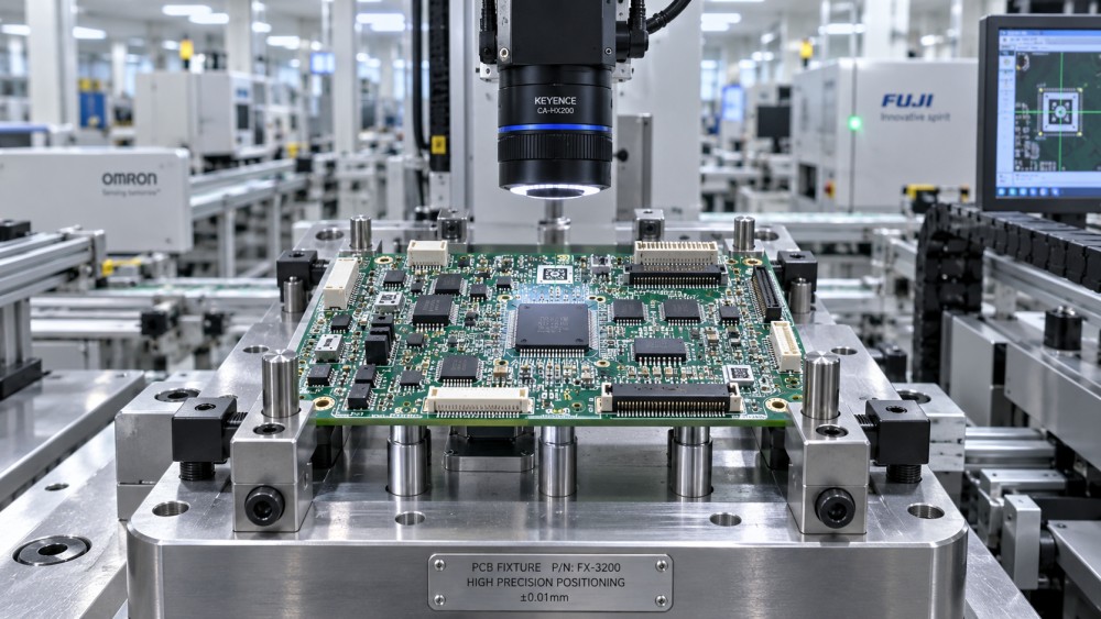
A practical review often maps the board journey through depaneling, paste printing, placement, reflow, selective soldering where applicable, manual assembly, inspection, and test. At each transfer, ask three questions: what physically locates the board, what measurement system recognizes its position, and what can change between cycles? The answers frequently identify simple issues such as worn locator pins, insufficient support under a flexible PCB, inconsistent clamp force, or a fixture design that references an unreliable edge.
Where Precision Positioning Has the Greatest Effect
The highest-value intervention is not always at the most visibly automated station. It is generally where position error combines with a narrow process window.
Connectors deserve particular attention because they sit at the intersection of cosmetic, mechanical, and electrical requirements. A connector can look acceptable on a camera inspection system while still creating downstream difficulty if its mating face is not positioned correctly relative to the enclosure or cable path. In these cases, locating from the PCB alone may not fully represent the functional condition. The fixture and inspection approach may need to reflect the actual interface.
Manual workstations are another frequent blind spot. A controlled soldering or fastening operation depends not only on the tool but on the board’s restraint and access angle. If an operator has to stabilize the assembly by hand, reposition it repeatedly, or work around obstructive clamps, positional variation becomes part of the method. Better ergonomics and better location control often reinforce each other rather than compete.
Choose Measurement Capability That Matches the Decision
Metrology should answer a production question, not merely generate more readings. Before specifying a vision system, coordinate measurement method, or fixture verification routine, define the decision it must support. Is the objective to confirm that a board is seated in a fixture? To verify placement after reflow? To distinguish machine drift from incoming board variation? To validate a new tooling concept during engineering build?
The required resolution, field of view, lighting, feature recognition method, and inspection cycle time follow from that decision. A highly detailed measurement routine can be counterproductive if it cannot operate at line pace or if it creates alarms that the team cannot consistently interpret. On the other hand, a fast camera check may be insufficient where a functional interface has tight mechanical relationships.
It is also worth separating the measurement system from the process under review. If a machine’s own vision system is used as the only evidence that its positioning is correct, errors in calibration or reference interpretation may remain hidden. Independent checks during setup, preventive maintenance, or process qualification provide a more credible basis for decisions. The frequency and extent of those checks should reflect product risk, volume, change frequency, and the stability already demonstrated by the line.
Avoid the “Tighter Is Always Better” Trap
Precision positioning is not a request to tighten every tolerance. Over-constraining a board can introduce stress, bowing, or damage, particularly with thinner substrates and assemblies containing sensitive components. Excessive clamp force can make a station seem stable while changing the board condition from its free state. Very tight fixture features may also increase loading time, raise maintenance demands, and make normal fabrication variation harder to accommodate.
The engineering goal is controlled constraint: enough contact points to locate the assembly in a repeatable, meaningful way, without forcing it into an artificial shape. Fixture designers commonly consider how the part is supported, located, and clamped as separate functions. Combining them carelessly is a common source of hard-to-diagnose variation.
Changeovers add another trade-off. A dedicated fixture may offer strong repeatability for a stable, high-volume product, while modular tooling can be more sensible for a mixed-product environment. Neither approach is automatically superior. The decision should include expected product life, engineering-change frequency, board family commonality, setup skill, replacement lead time, and the cost of validating a new configuration.
Turn Positioning Into a Managed Yield Variable
The most effective projects do not treat tooling, machine programming, inspection, and maintenance as separate workstreams. They establish a small set of positional indicators tied to known defects or critical interfaces, then review those indicators alongside yield and rework data. This creates a clearer link between physical process behavior and business impact.
Useful questions during implementation include:
- Which defects are location-sensitive, and at what operation do they first become detectable?
- Does the process reference functional features or only convenient manufacturing features?
- What happens after fixture cleaning, tool replacement, program revision, or product changeover?
- Can operators recognize a seating or clamping problem before the assembly enters the next process?
- Is there a documented method for checking fixture wear, calibration status, and locator condition?
These questions can expose a gap that capital equipment alone will not solve: process ownership. A precision fixture without a verification routine eventually becomes an unmeasured variable. A well-designed vision program loses value when engineering changes do not update the underlying reference data. Consistency depends on keeping the physical setup, digital recipe, and inspection logic aligned.
Using Industrial Intelligence Without Losing Shop-Floor Context
Positioning decisions increasingly sit within a broader manufacturing landscape. Tool availability, component-package changes, export restrictions affecting equipment supply, evolving safety practices, and the move toward connected torque and measurement tools can all influence an implementation plan. Yet external trends should inform the project, not replace direct process evidence.
The Global Precision Tools & Welding Matrix (GPTWM) examines this “last mile” of industrial manufacturing through industrial assembly, metal joining, and precision metrology intelligence. Its Strategic Intelligence Center brings together perspectives from metrology, electro-mechanical tool design, and industrial economics to connect technology developments with practical deployment questions. For electronics operations, that broader view is useful when a positioning issue crosses boundaries: for example, when a fixture decision affects manual fastening, inspection capability, maintenance planning, or sourcing risk.
The relevant lesson is straightforward: precision tools and digital systems create value only when they improve a specific manufacturing decision. Whether evaluating intelligent torque control, visual alignment, fixture materials, or measurement workflows, the project should return to the same test: does this make the assembly easier to locate, verify, and reproduce under normal production conditions?
A Better Starting Point for the Next Yield Review
When yield stalls, begin with the products and stations where rework is concentrated rather than launching a line-wide precision initiative. Trace the physical datum from incoming board to final verification. Observe how the assembly is actually loaded, supported, clamped, recognized, and measured. Compare that reality with the design intent and with the coordinate assumptions inside production programs.
The result may be a modest corrective action: replacing worn locating elements, adding support beneath a flexible area, revising a local fiducial strategy, or updating an inspection reference. In more demanding applications, it may justify a redesigned fixture and a more formal measurement plan. The right scope is the one that removes a demonstrated source of variation while remaining maintainable by the people running the line every day.
Higher yield is rarely produced by one dramatic adjustment. It is built by making location, measurement, and process intent agree—consistently enough that a good board is not dependent on a fortunate setup or an experienced operator noticing a subtle misalignment.
Related News
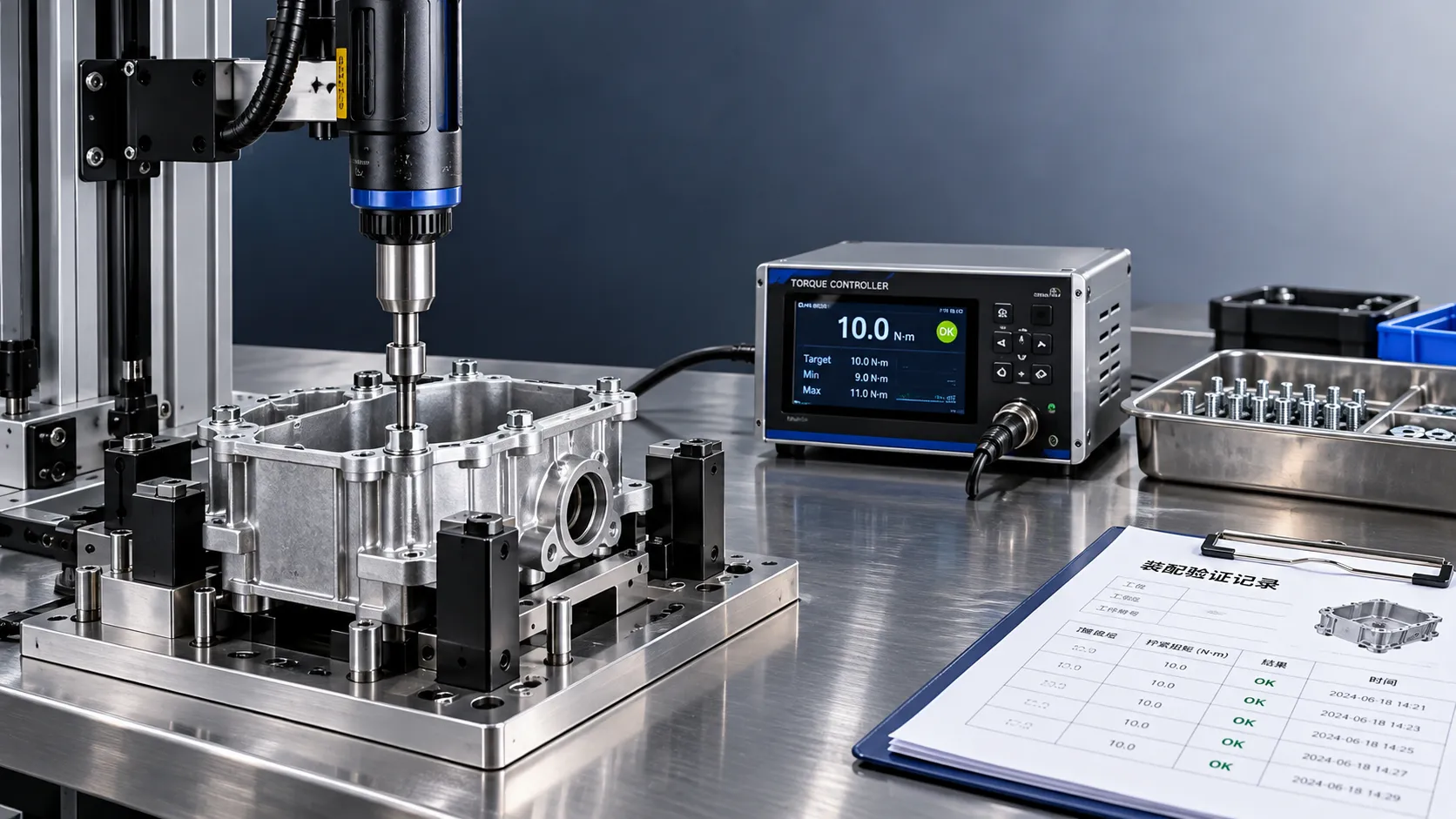
Torque System Suppliers: How to Assess References for Assembly Projects
Explore supplier and solution references torque systems buyers should verify. Assess assembly fit, traceability, and support to reduce risk and choose with confidence.

Equipment Application Guidance for the Middle East: Managing Heat and Dust
Explore application guidance Middle East teams can use to manage heat and dust, protect welding equipment, batteries and precision tools, and reduce downtime. Get practical tips.
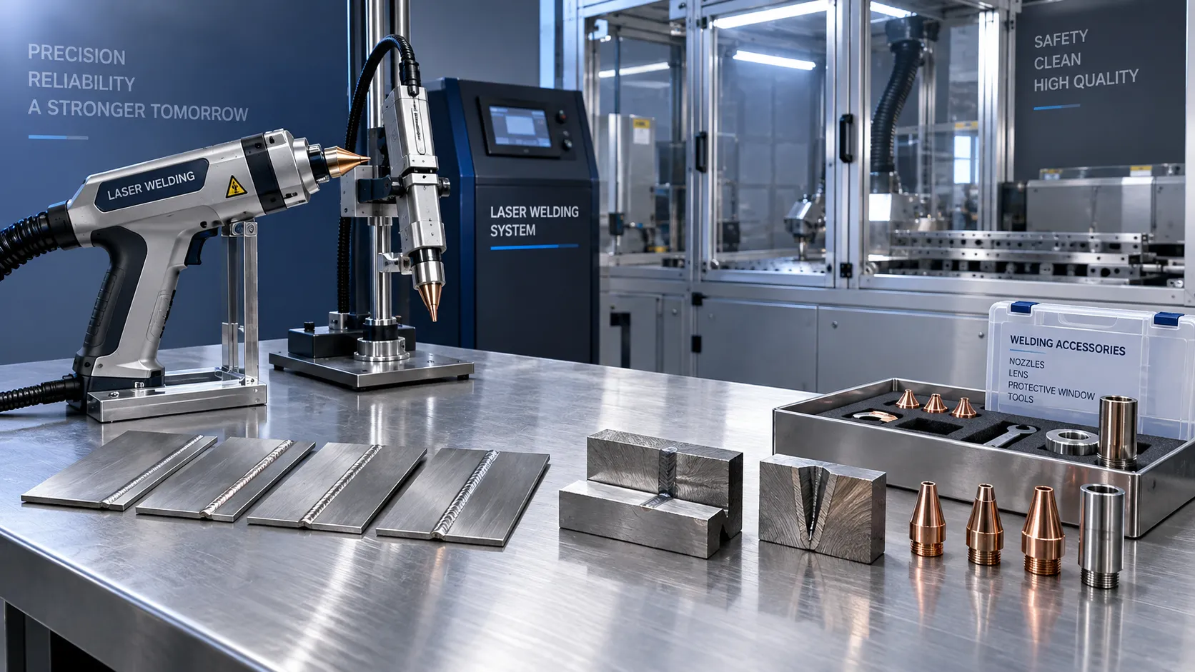
Choosing a Handheld Laser Welding Supplier: Weld Trials, Training, and Service
Choose a handheld laser welding supplier with proven weld trials, safety training, and reliable service. Learn what to verify before buying to reduce downtime and protect your investment.
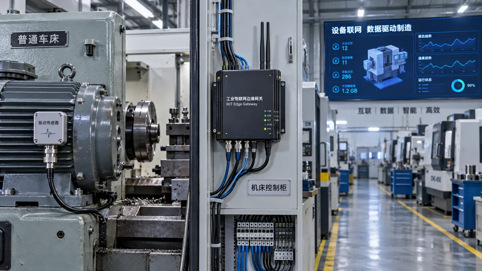
Choosing an Industrial IoT Platform: Key Criteria for Legacy Equipment
Choose an industrial IoT platform for legacy equipment with confidence. Discover key checks for connectivity, data integrity, security, and lifecycle costs before investing.

In-House vs. Outsourced Aircraft Maintenance: Comparing Total Costs
Compare aerospace maintenance cost for in-house vs. outsourced aircraft upkeep. Discover hidden expenses, downtime impacts, and break-even factors to find the best fit for your fleet.
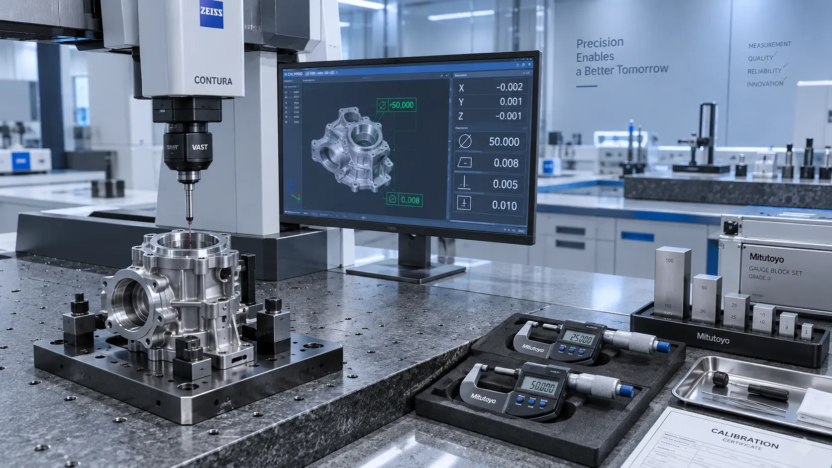
How to Select High-Precision Measuring Instruments for Tight-Tolerance Production?
High-precision measuring instruments are essential for tight-tolerance production. Learn how to evaluate accuracy, repeatability, environment, calibration, and data integration.
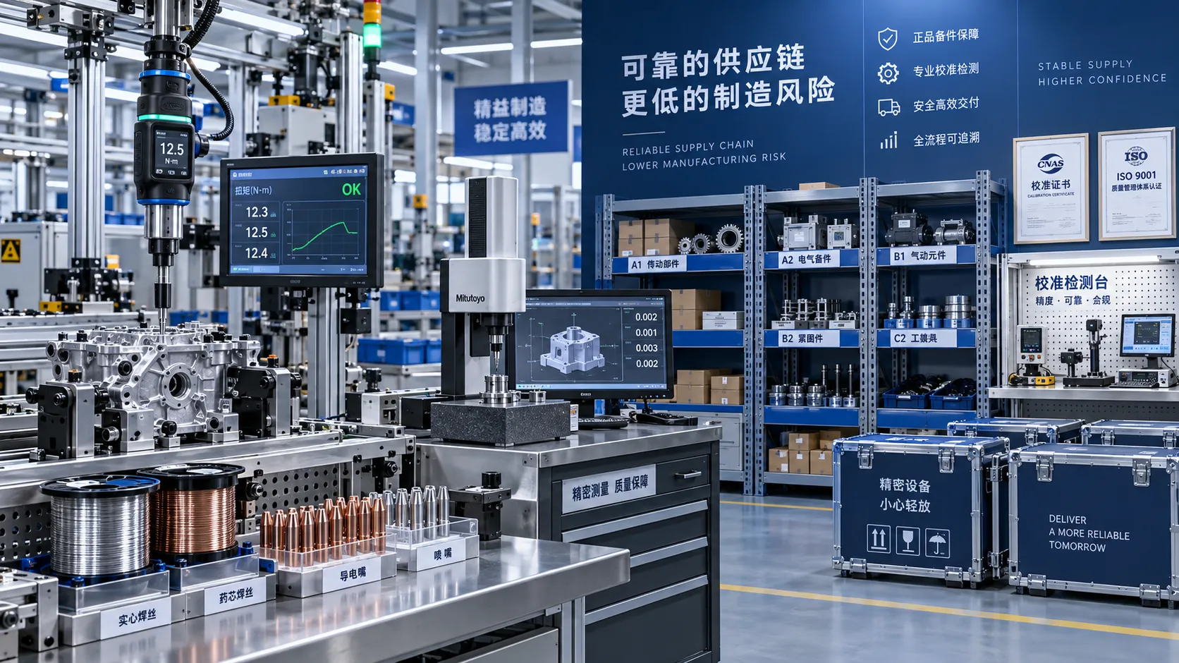
How Industrial Innovation Supplier Networks Reduce Sourcing Risk for Manufacturers
industrial innovation supplier network insights help manufacturers reduce sourcing risk, control lifecycle costs, and choose reliable tools, services, and suppliers with confidence.
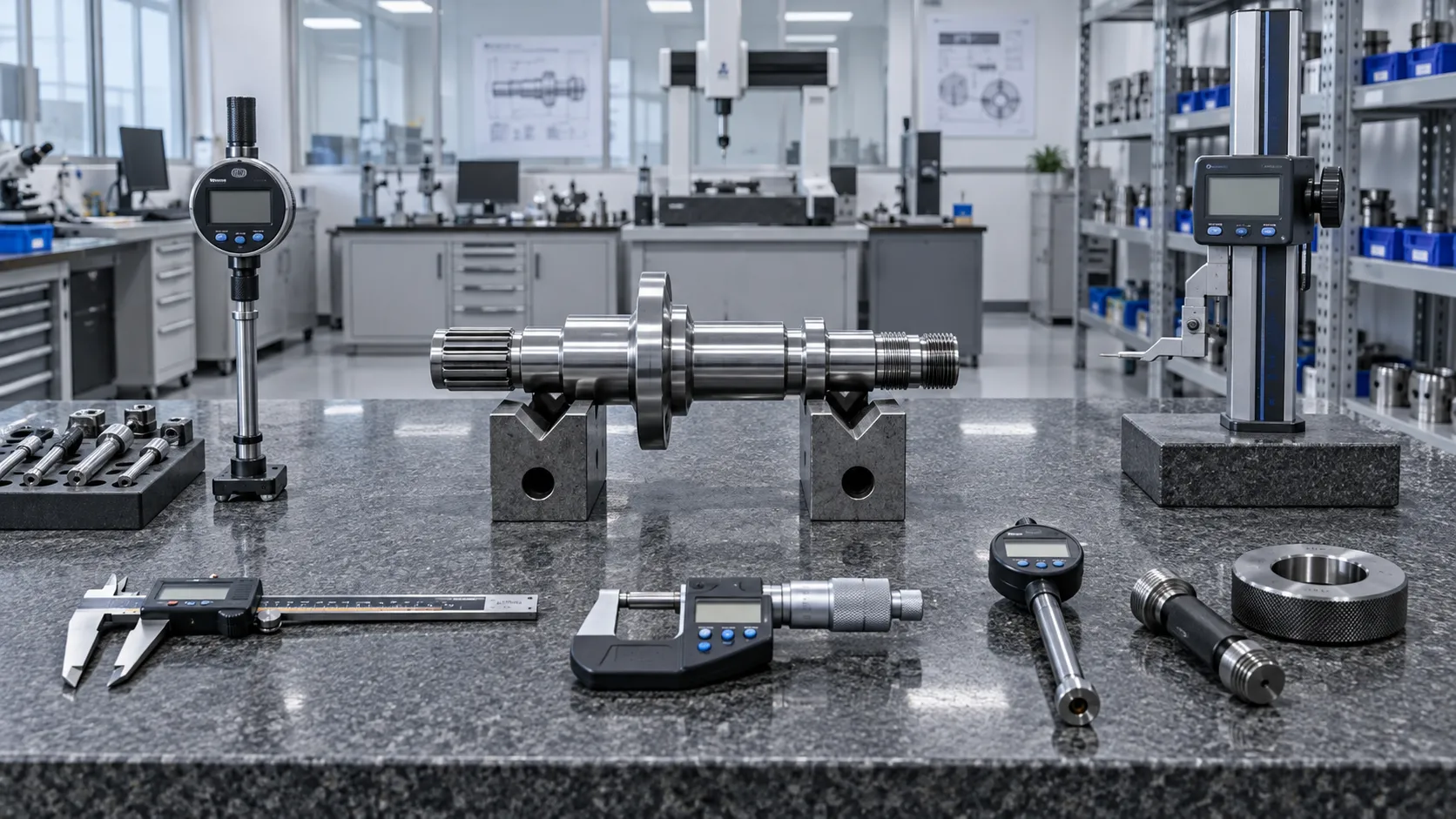
Which Precision Measuring Tools Are Best for Incoming Inspection?
Which precision measuring tools are best for incoming inspection? Explore calipers, micrometers, gauges, CMMs, and smarter strategies to prevent costly defects.
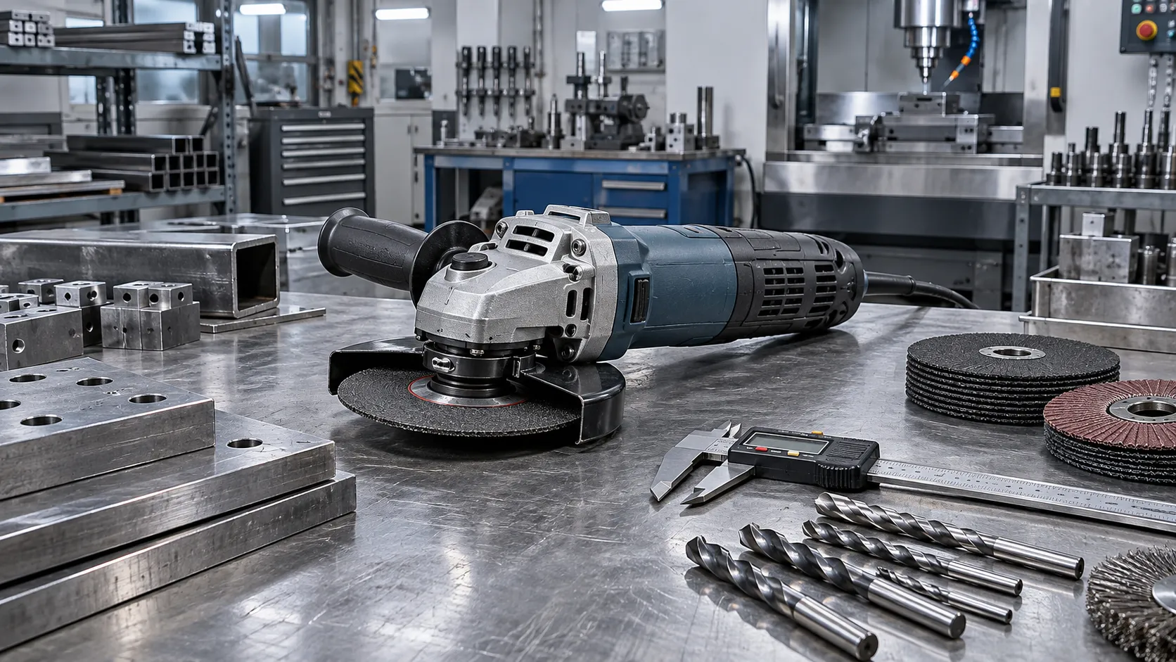
Are Lower-Cost Metalworking Tools More Likely to Fail Early?
Are cheaper metalworking tools more likely to fail early? Explore duty cycle, build quality, and total ownership costs to make smarter buying decisions.
Related News
- 00
0000-00
Equipment Application Guidance for the Middle East: Managing Heat and Dust - 00
0000-00
Choosing an Industrial IoT Platform: Key Criteria for Legacy Equipment - 00
0000-00
How to Select High-Precision Measuring Instruments for Tight-Tolerance Production? - 00
0000-00
How Do Advanced Manufacturing Methods Improve Batch Consistency? - 00
0000-00
Precision Positioning in Electronics Manufacturing: A Practical Route to Higher Yield
Prof. Marcus Chen
Weekly Insights
Stay ahead with our curated technology reports delivered every Monday.