
Laser Welding for Thin Metals: How to Prevent Distortion and Porosity





Laser Welding for Thin Metals: How to Prevent Distortion and Porosity
Laser welding is often selected for thin metal assemblies because it can place energy into a narrow, controllable zone. That advantage is real, but it can create false confidence. A thin sheet, tube, stamped housing, battery enclosure, or cosmetic stainless assembly has very little thermal mass and very little tolerance for process variation. A weld can appear clean at first inspection while carrying internal porosity, excessive penetration, edge collapse, or distortion that appears only after the part is released from its fixture.
For technical evaluators, the question is not simply whether a laser source can make a weld. The more useful question is whether the complete laser welding cell can repeatedly produce an acceptable joint across expected changes in material lot, part fit-up, coating condition, operator setup, and production pace. Distortion and porosity are rarely isolated machine faults. They are usually symptoms of an energy, material, shielding, or fixturing system that has not been evaluated as a whole.
Thin-gauge work rewards disciplined development. The window between insufficient fusion and excessive heat input may be narrow, particularly for reflective alloys, thin stainless steel, aluminum, galvanized material, and dissimilar-thickness joints. A stable result depends on understanding where heat goes, how vapor escapes from the molten pool, and how the part is constrained before the laser is ever switched on.
Why Thin Metal Distorts So Easily
Distortion comes from uneven thermal expansion and contraction. During laser welding, the joint area heats and expands rapidly while the surrounding sheet remains cooler and restricts that movement. As the weld solidifies and cools, the localized contraction pulls the part out of plane. On a thicker fabrication, the effect may be absorbed by the section stiffness. On a thin cover, flange, or precision bracket, it can change flatness, hole position, gap condition, or the appearance of a visible surface.
A laser’s concentrated beam generally reduces the width of the heat-affected zone compared with broader arc processes, but “lower heat input” does not automatically mean “no distortion.” Excessive power, slow travel, an oversized focal spot, repeated repair passes, or an unnecessary weave pattern can still put more heat into the part than the geometry can tolerate. The same risk appears when a process relies on a large weld pool to bridge a gap that should have been corrected in forming or fixture design.
Joint configuration matters as much as beam settings. A lap joint can trap heat between layers and create local buckling. A butt joint with inconsistent edge preparation can force the beam to melt one side more than the other. Small tack welds may seem harmless, yet poorly placed tacks can lock stress into a thin panel before the continuous seam begins. The part’s release sequence also matters: a component that looks stable in a rigid fixture may spring after unclamping.
The practical aim is not to eliminate all thermal movement; that is rarely possible. It is to make movement predictable, small enough for the functional requirement, and consistent enough that downstream assembly does not become a sorting operation.
Control Heat Input Before Trying to Correct the Part
The first response to weak fusion is often to increase laser power. For thin metals, that shortcut frequently trades one defect for another. Evaluation should consider power together with travel speed, focal position, beam diameter, pulse or modulation behavior where applicable, wobble strategy, and seam geometry. These factors determine power density and interaction time; neither can be understood from a single power setting alone.
A focused beam placed incorrectly relative to the material surface can produce unstable penetration even when nominal power and speed remain unchanged. Focus tolerance becomes especially important on formed parts, where height variation can be greater than the allowable process window. If the workpiece is not consistently located, process engineers may compensate with wider beam motion or higher energy. That may make the weld visually more forgiving while increasing the risk of distortion, undercut, and spatter.
For sensitive joints, parameter development should begin with representative coupons that reproduce production realities: actual thickness combinations, surface condition, joint gap, seam orientation, and restraint. Flat clean samples are useful for initial setup, but they are poor evidence that a cell will handle stamped, coated, or slightly variable production parts. Cross-sections, bend or tensile testing where relevant, leak testing for sealed products, and dimensional inspection after unclamping reveal different failure modes. A camera image of a bright, smooth seam is not enough.
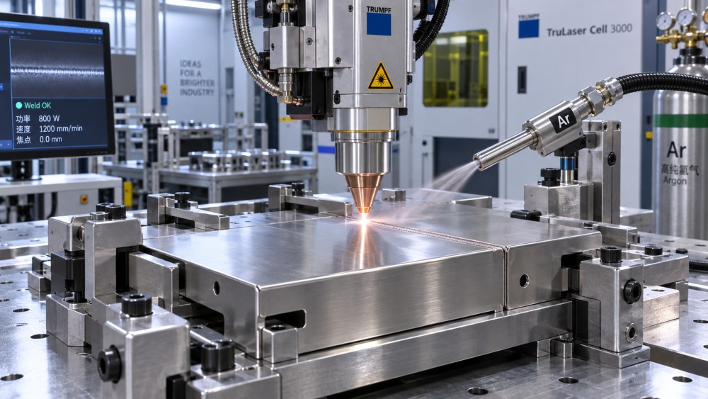
Sequence planning deserves equal attention. Long continuous seams concentrate shrinkage in one direction. Segmenting the path, welding from balanced locations toward the center, alternating opposing sides, or using a controlled skip sequence can reduce accumulated pull. The best approach depends on the part’s stiffness and sealing requirements, so it should be verified on the actual assembly rather than copied from a different product family.
Fit-Up Is a Process Parameter, Not an Upstream Assumption
Laser welding is less tolerant of uncontrolled gaps than many teams expect. A narrow, high-energy beam is highly effective when it reaches both intended faying surfaces in a repeatable position. If the gap changes along the seam, the molten pool may drop through, fail to bridge, or form an irregular root profile. Attempting to compensate solely through higher power or broader oscillation can widen the heat-affected zone and reduce the dimensional advantage that justified the laser process.
Technical evaluation therefore needs a measurable fit-up strategy. This includes incoming component variation, stamping burr direction, edge quality, fixture wear, clamp force, datum scheme, and the effect of thermal expansion during welding. A fixture should locate the part without imposing unnecessary stress, hold the seam closed where required, and provide access for shielding gas and beam delivery. Over-clamping can conceal poor part fit-up during welding and create a pronounced springback when the clamp opens. Under-clamping allows the joint to move before the pool solidifies.
For thin sheet, copper backing bars, heat sinks, or carefully designed support surfaces can help remove heat and prevent local collapse. They are not universal solutions. A backing arrangement changes cooling rate and can affect penetration, root shape, and access for gas coverage. Its material, contact consistency, and maintenance condition need to be part of the qualification plan.
Porosity Starts with Contamination, but It Does Not End There
Porosity forms when gases become trapped as the weld pool solidifies. In thin metal laser welding, the pool can be small and fast-freezing, leaving limited time for gas bubbles to rise and escape. Surface contamination is a familiar cause: oils, drawing compounds, moisture, fingerprints, paint residues, adhesive traces, and oxide layers can introduce volatile material into the weld zone. A cleaning step that is adequate for general fabrication may not be adequate for a narrow, high-energy laser process.
Material condition requires closer scrutiny when coatings are involved. Zinc-containing coatings, for example, can generate vapor under the laser. If vapor cannot escape from a lap joint or tight faying interface, it may destabilize the keyhole and leave pores, spatter, or intermittent fusion. The appropriate solution may involve joint design, venting strategy, controlled gap, coating management, beam placement, or a different process route. It should not be assumed that one parameter set will work across every coated sheet supplier or coating condition.
Shielding gas has two jobs: it protects the molten metal from the atmosphere and influences the local plume around the interaction zone. Gas type, purity, flow stability, nozzle shape, nozzle-to-work distance, and direction all matter. Too little coverage can allow oxidation and unstable surface behavior. Excessive or badly directed flow can disturb a small molten pool or entrain surrounding air. A gas line can appear functional yet still deliver inconsistent results because of leaks, contaminated hoses, poor nozzle alignment, or spatter buildup.
Porosity can also arise from an unstable keyhole. When power density is high enough to create vapor-driven penetration, the keyhole must remain sufficiently stable for the weld pool to solidify without trapping voids. Surface reflectivity changes, focus drift, inconsistent travel motion, and rapid changes in joint geometry can all affect that stability. This is why a process that works on stainless steel may not transfer directly to aluminum or copper alloys, even when sheet thickness is similar.
What a Credible Process Evaluation Should Demonstrate
A laser welding supplier or internal engineering team should be able to discuss more than source power and headline speed. The evaluation should show how the process responds to expected variation and how quality will be checked when production begins. The following questions are useful because they expose whether the proposed solution addresses the complete joining system.
- What thickness range, alloy condition, coating state, and joint design were used during trials?
- How is focal position maintained when part height, seam location, or fixture condition changes?
- What fit-up range can the process tolerate without relying on excessive heat input?
- How are surface preparation, gas delivery, and consumable cleanliness controlled on the shop floor?
- Which inspection methods confirm penetration, internal soundness, leak integrity, and post-weld geometry?
- What happens after a planned stop, a restart, a fixture change, or replacement of protective optics?
The last point is often underestimated. Optical contamination, variation in protective windows, changes in beam delivery, and minor fixture damage can shift a process away from its validated condition. A robust cell needs defined checks, documented settings, and a practical response when monitoring indicates drift. For automated lines, seam tracking, vision, power monitoring, or other sensing methods may be appropriate, but their value depends on how alarms are interpreted and acted upon. Monitoring is not a substitute for sound joint design.
Handheld and Automated Laser Welding Require Different Judgments
Handheld laser welding can be useful for repair, low-volume fabrication, and assemblies where rigid automation is difficult to justify. Yet thin metals expose the limits of manual consistency. Torch angle, stand-off distance, travel speed, overlap at starts and stops, and operator response to a changing gap can all alter heat input. A process that performs well in a demonstration may need substantial procedure control before it is suitable for a dimensionally sensitive production part.
Automation offers repeatable path control and can support controlled clamping, coordinated gas delivery, and in-process monitoring. It does not remove the need for development. If incoming parts vary beyond the fixture and sensing strategy, an automated cell can repeatedly create the same defect at high speed. The choice should be based on part volume, geometric tolerance, access, mix variability, repair needs, safety arrangements, and the organization’s ability to maintain the process—not on a general claim that one format is inherently superior.
Build the Decision Around the Last Mile
The most consequential laser welding decisions are often made at the last mile of manufacturing: the relationship between formed part quality, fixturing, heat control, inspection, and the person or system operating the cell. This is where a nominally capable technology either becomes a reliable production process or a recurring source of rework.
At The Global Precision Tools & Welding Matrix (GPTWM), the focus is on connecting metal joining practice with the broader intelligence needed for manufacturing decisions. That includes watching the development of handheld laser welding safety, precision metrology, intelligent assembly controls, material and export conditions, and the practical limits of industrial tools. For thin-metal projects, metrology is especially relevant: distortion cannot be controlled credibly if the organization has not defined how flatness, angular change, seam position, and release-state movement will be measured.
Before approving a laser welding solution, evaluate representative parts under realistic restraint and inspect them after they cool and leave the fixture. Confirm the acceptable defect criteria with the applicable product requirements, then challenge the process with normal variation rather than only ideal samples. If the weld remains sound, dimensions remain controlled, and the method for detecting drift is clear, the process has moved beyond a promising demonstration toward a defensible manufacturing decision.
Related News
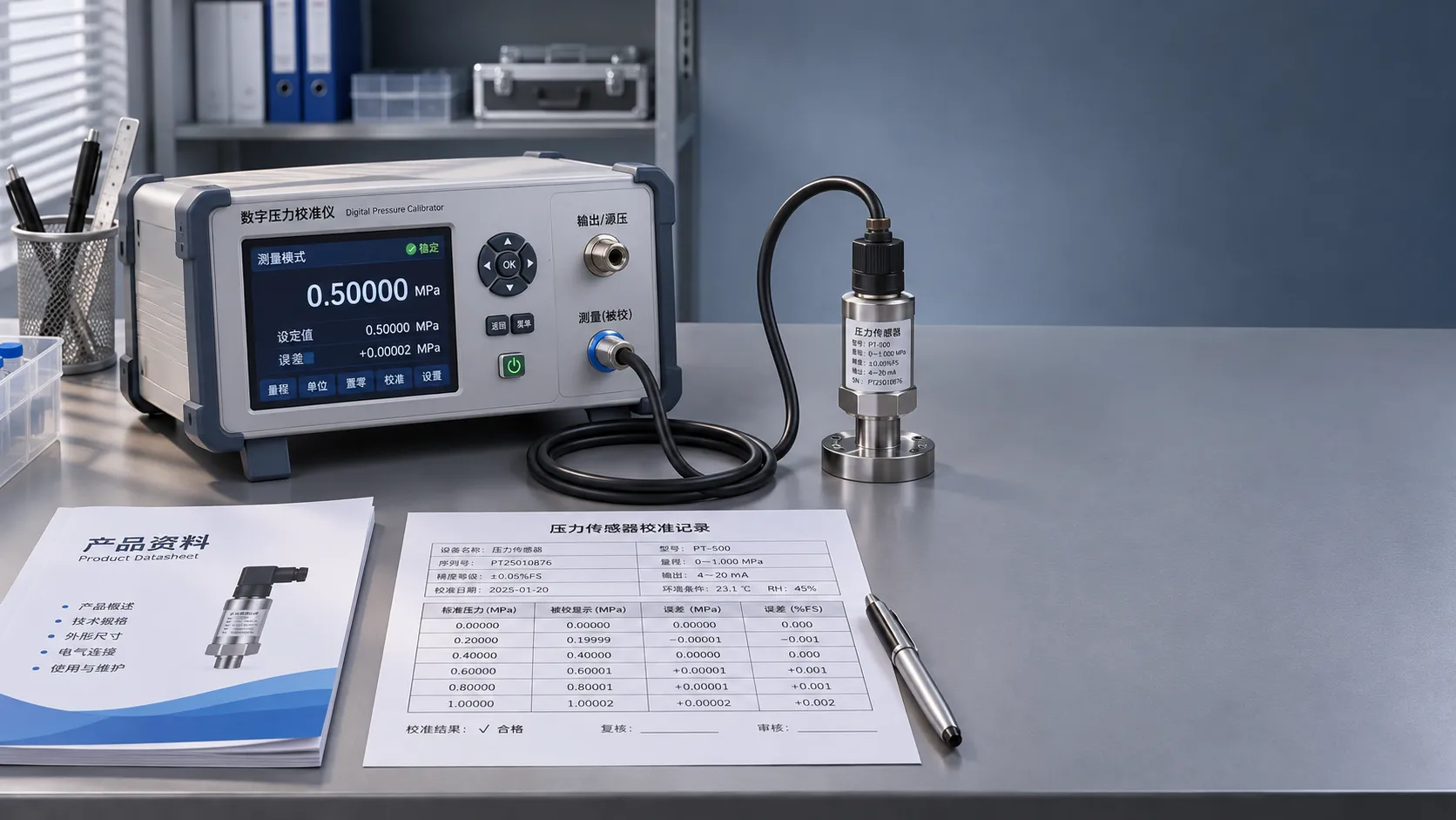
Calibration Tool Specifications: Where to Find and Verify Product Data
Explore product information resources for calibration tools and learn how to verify specifications, certificates and traceability before you buy.
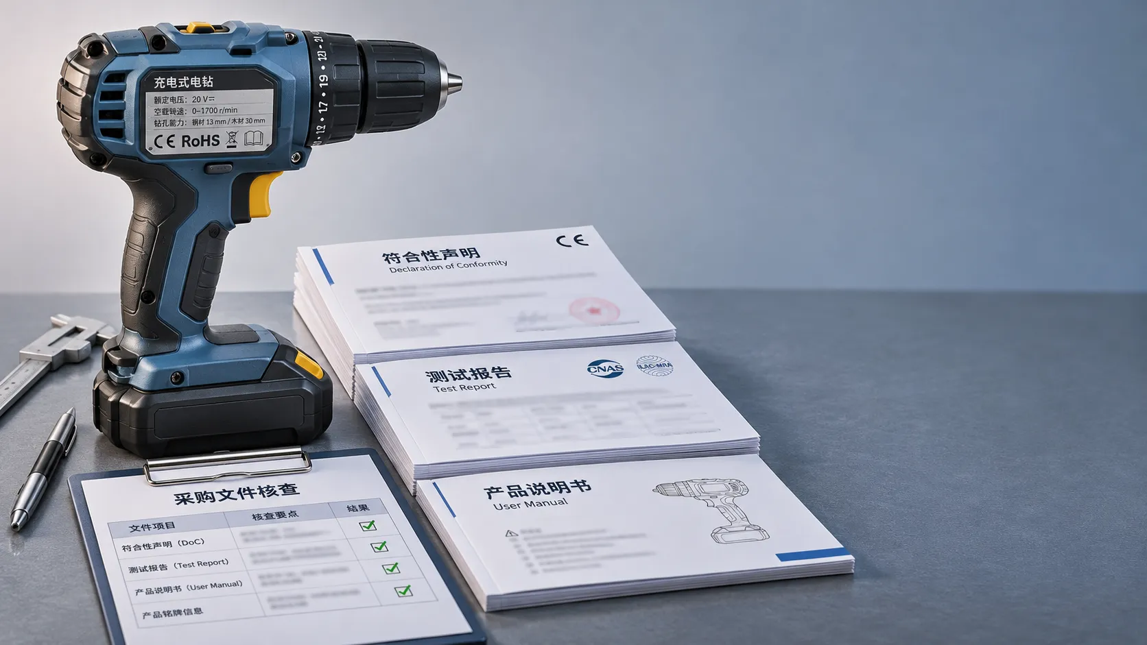
Choosing CE-Marked OEM Tools: Documents Buyers Should Check
Buying OEM tool solutions CE certified for Europe? Discover the documents to check, avoid costly compliance gaps, and choose suppliers with confidence.
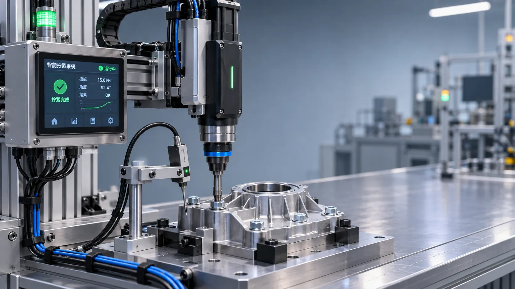
Industrial Innovation Trends: Where Manufacturers Should Invest
Explore industrial innovation trends in fastening, metrology, laser welding, and connected tools—and discover where manufacturers should invest.
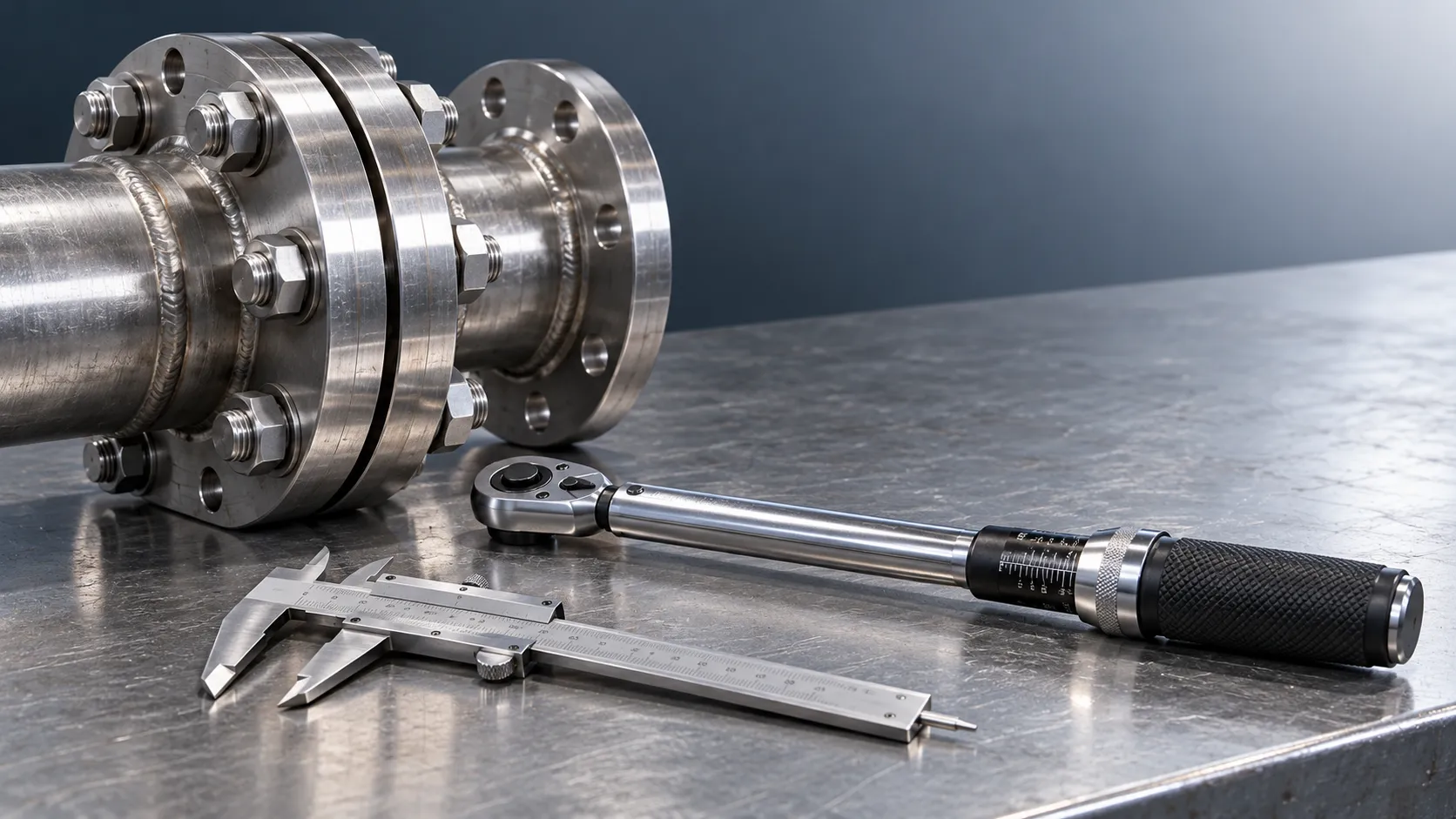
Industrial Assembly Specifications: How to Define Tolerances and Torque
Explore specification-oriented articles on industrial assembly and learn how to define tolerances, validate torque settings, and improve joint reliability.
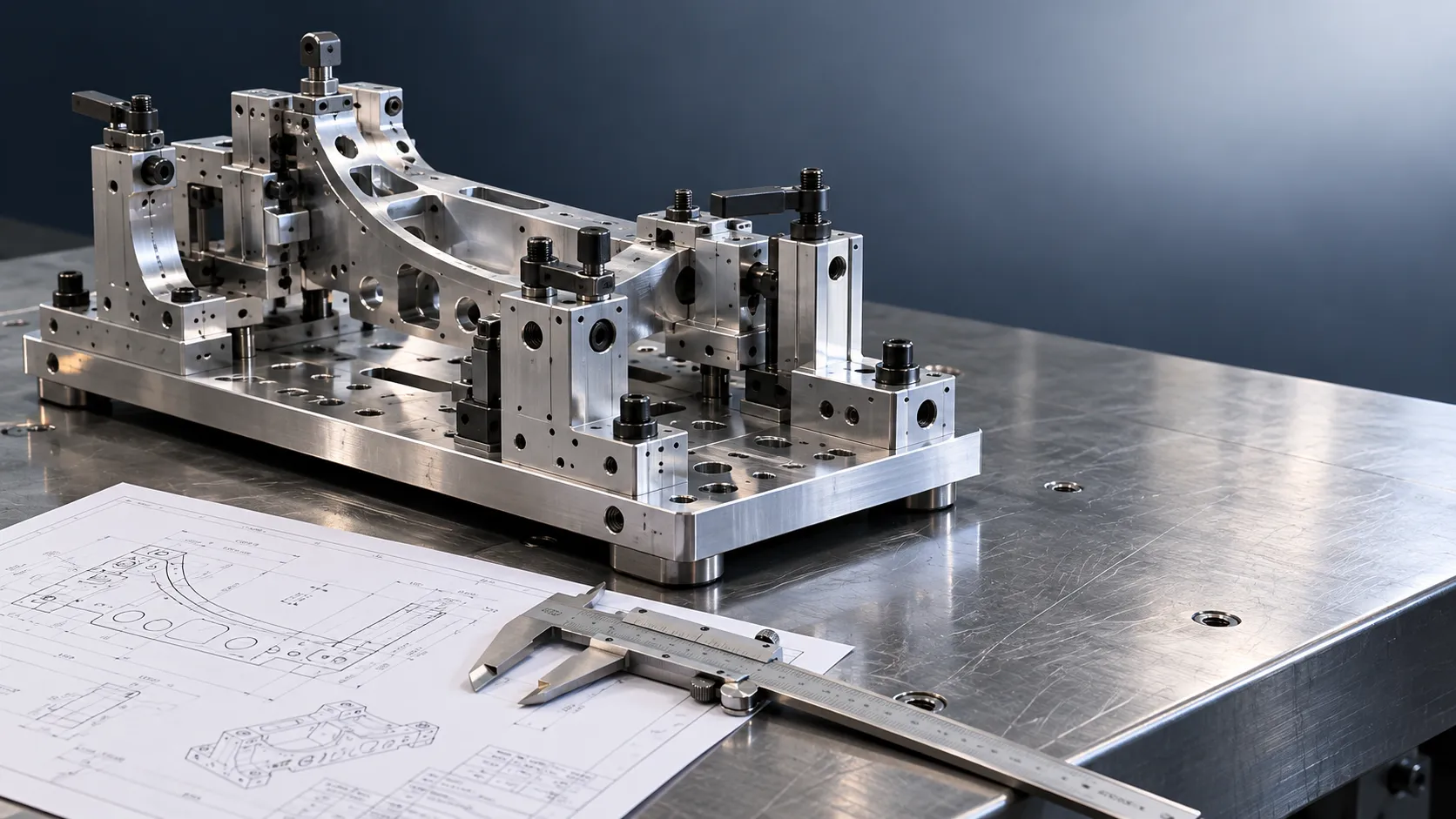
AMS Specifications for Aerospace Tooling: What Do They Cover?
Aerospace tools AMS requirements can cover materials, processes and documentation. Learn how to verify compliance and assess finished-tool acceptance.
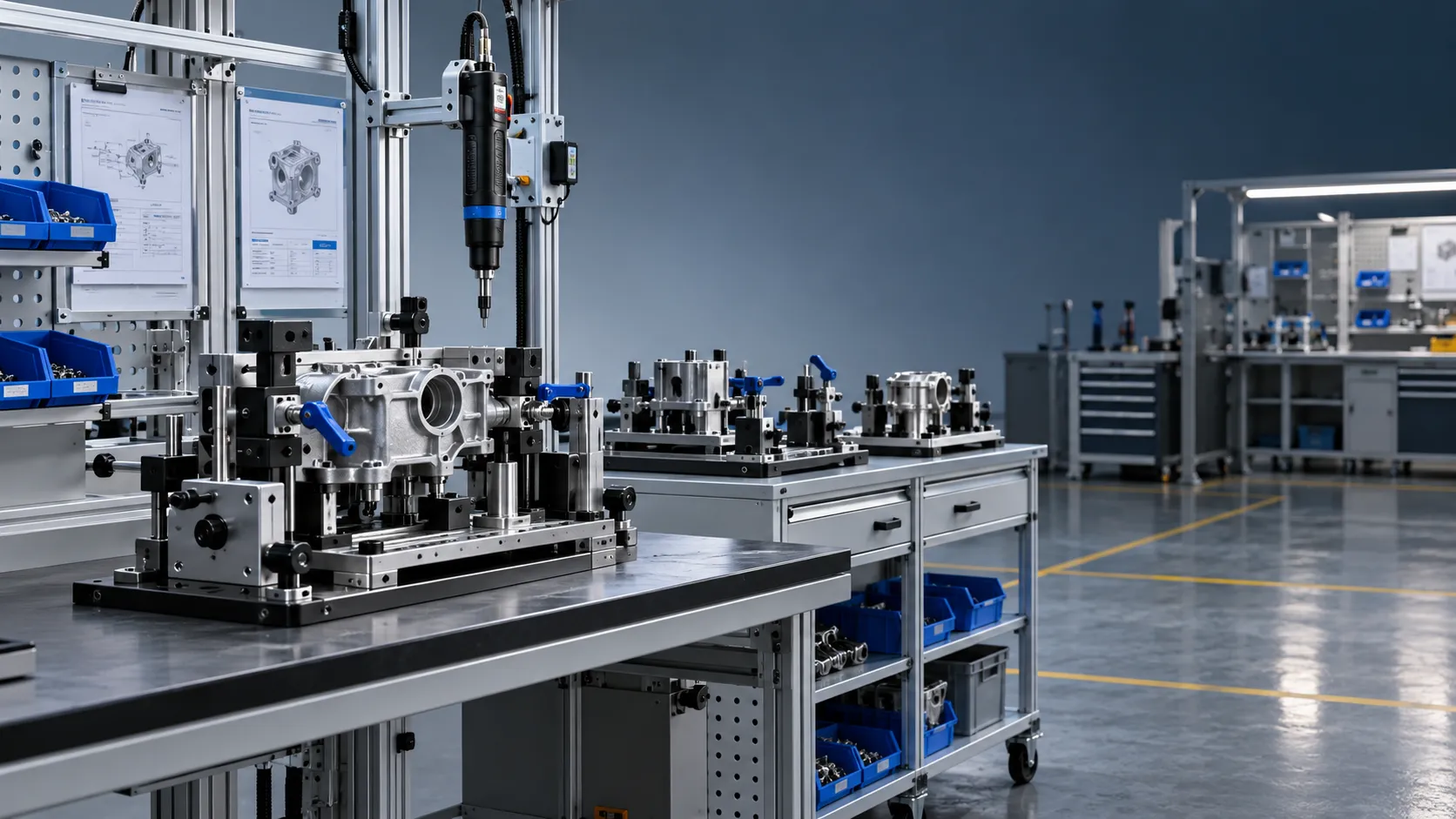
Choosing Industrial Assembly Solutions for High-Mix Production Lines
Choose industrial assembly solutions for high-mix production with practical guidance on changeovers, quality, traceability, automation, and total cost.
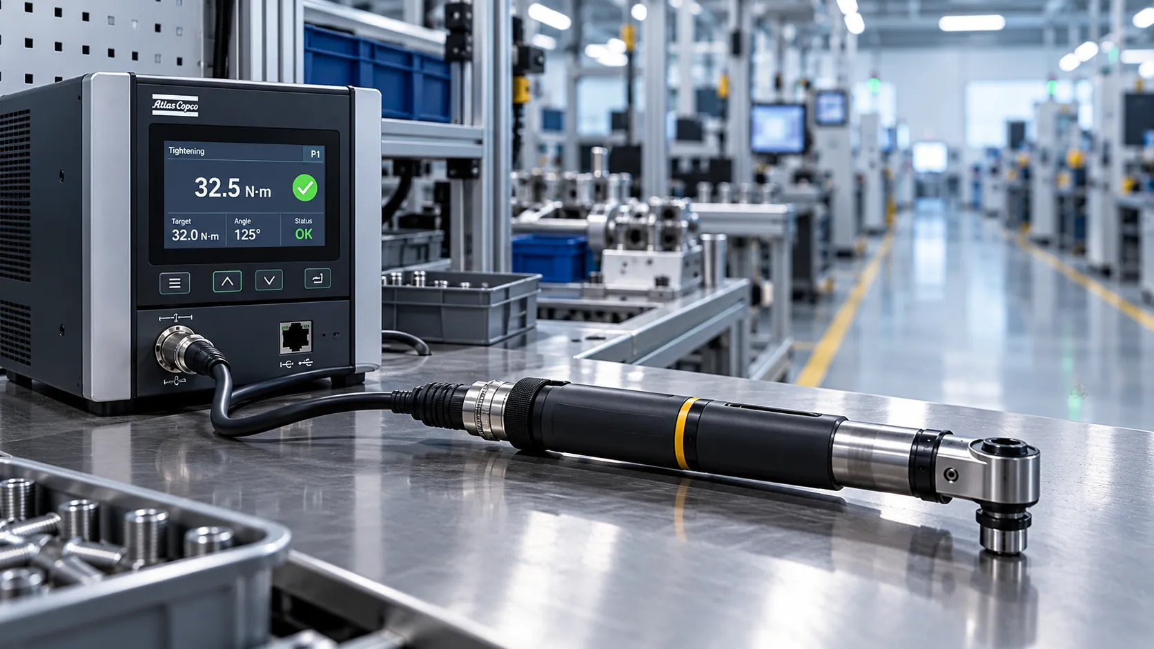
Choosing an Industrial IoT Tools Distributor: Integration and Support Criteria
Choose an industrial IoT tools distributor with confidence. Compare integration, support, security, and lifetime costs to avoid hidden risks and protect production.
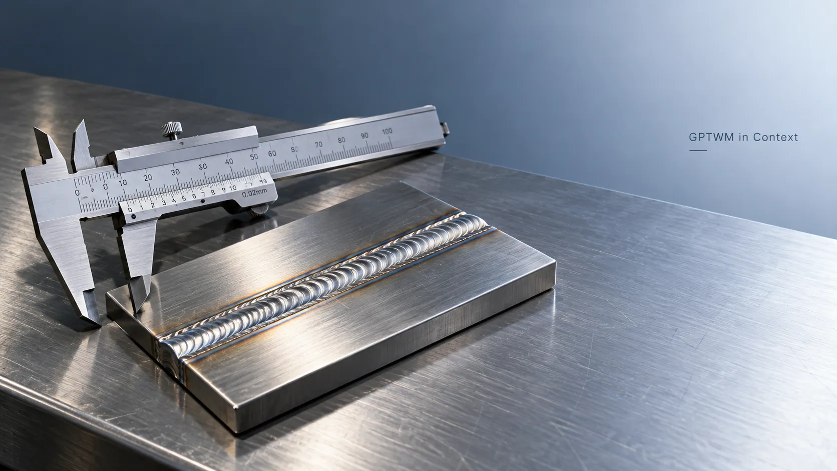
What Does GPTWM Mean? How to Verify Its Meaning in Context
What does gptwm mean? Explore its industrial context and learn how to verify the full name, publisher, and supporting sources before relying on its claims.
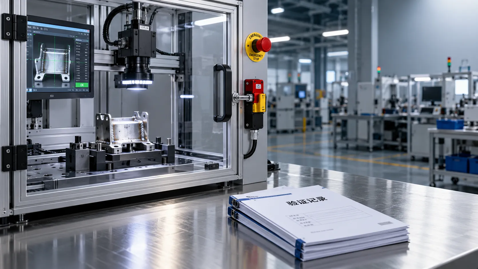
Industrial AI Compliance Guide: What to Check Before Factory Deployment
Use this industrial intelligence compliance guide to check safety, legal duties, cybersecurity, and validation before factory AI deployment. Explore the checklist to close critical gaps.
Related News
- 00
0000-00
Laser vs. Resistance Spot Welding: Which Fits Automotive Body Assembly? - 00
0000-00
How to Choose Welding Tools for Field Repair Work - 00
0000-00
What Welding Equipment Documents Should Suppliers Provide? - 00
0000-00
Welding Fume Extraction PPE: When Respirators Are Not Enough for Shop Safety - 00
0000-00
Laser Welding for Thin Metals: How to Prevent Distortion and Porosity
0000-00
Welding Metallurgy Expert
Weekly Insights
Stay ahead with our curated technology reports delivered every Monday.