
How to Select Vernier Precision Calipers for Tight-Tolerance Machining Inspection





A caliper that looks precise is not automatically suitable for tight-tolerance machining inspection. The correct choice depends on whether its usable accuracy, resolution, jaw geometry, measuring range, and verification routine match the dimensions being accepted or rejected. For many machined parts, vernier precision calipers are practical, durable tools for fast checks. They are not, however, a universal substitute for micrometers, bore gauges, height gauges, or dedicated go/no-go gauges.
The first decision is therefore not “Which caliper is the most precise?” It is “Which measurements can this caliper reliably control in this process?” A well-selected vernier caliper supports consistent inspection and early detection of machining drift. A poorly matched one can create false confidence, especially when the tolerance is close to the tool’s practical measurement capability.
Start With the Tolerance, Not the Caliper Catalog
Before comparing materials, scale markings, or supplier claims, list the dimensions that must be measured: outside diameters, widths, step dimensions, depths, internal diameters, and feature locations. Then separate routine process checks from final acceptance measurements. These two tasks may require different tools.
A caliper is generally strongest when the feature is accessible, the contact surfaces are broad enough for the jaws to seat consistently, and the tolerance leaves sufficient room for repeatable manual measurement. It is less suitable when a small change in jaw angle, contact force, burr condition, or operator technique can determine whether a part passes.
Resolution is only the smallest increment shown on the scale. It does not guarantee that the user can repeatedly obtain that value on an actual part. Accuracy describes how closely a reading agrees with the true dimension under controlled conditions. Repeatability concerns whether repeated measurements of the same feature produce closely grouped results. For tight machining tolerances, repeatability in the real inspection environment is often the more immediate concern.
If the allowable variation is narrow relative to the uncertainty created by the tool, the part geometry, and the measurement method, move to a more specialized instrument. An outside micrometer is often a better choice for critical external diameters. A bore gauge, internal micrometer, or plug gauge may be needed for close-tolerance holes. A depth micrometer may be more dependable for critical recesses or shoulders than the depth rod on a caliper.
Choose a Measuring Range That Preserves Control
Range should be selected from the largest feature that must be measured, with enough margin for comfortable access. It is tempting to standardize on the longest caliper available, but an oversized tool is not always the best daily instrument. Longer beams can be more awkward to align, require more hand support, and make small features harder to inspect consistently.
A compact caliper is often easier to control for small turned parts, fittings, stamped components, and short milled features. A longer model is justified when the production mix includes larger shafts, housings, welded assemblies, or broad fabricated parts. Where both small and large features are inspected regularly, two properly sized tools may provide better measurement discipline than forcing one long-range caliper into every task.
Also consider access, not just nominal dimension. A part may fit within the stated range but still be difficult to measure if nearby flanges, threads, chamfers, retaining rings, or fixture surfaces prevent the jaws from sitting squarely. Internal jaws need enough clearance to enter the feature without rubbing adjacent surfaces. The depth rod needs a stable reference surface and clear travel to reach the bottom of the feature.
Jaw Design Determines Whether a Reading Is Meaningful
Caliper jaws are versatile, but their versatility has limits. Outside measuring jaws work well on flat, parallel surfaces and on sufficiently large cylindrical surfaces. They are less dependable on very small diameters, narrow lands, tapered faces, interrupted surfaces, or parts with thin edges. On a round workpiece, even a minor tilt can produce a reading that does not represent the true diameter.
Inside jaws require even more attention. Internal measurements taken near the mouth of a bore may differ from those deeper in the bore, particularly when the hole is tapered, bell-mouthed, distorted, or affected by finishing operations. A caliper can indicate that a bore is changing, but it may not establish a reliable final size for a critical bore.
Depth measurement is another common source of avoidable error. The beam must remain perpendicular to the reference face, the base must sit fully on a clean surface, and the depth rod must contact the actual bottom rather than a radius, chip, burr, or sloped area. For shallow counterbores and noncritical slots, the depth function can be efficient. For a controlled depth that affects assembly fit or safety clearance, a dedicated depth instrument is usually easier to standardize.
Match the caliper to the feature, not merely the dimension
Material and Construction Affect Long-Term Reliability
For shop-floor use, stainless steel construction is generally preferred because it resists corrosion, holds up better against routine handling, and is easier to keep clean. Smooth slider travel matters more than a loose or overly stiff feel. The carriage should move without binding, but it should not shift under its own weight or from light contact with the part.
Inspect the beam, jaws, locking arrangement, and scale finish before selecting a model. Scale markings must remain readable under local lighting conditions. The vernier scale should be sharply engraved or clearly marked enough to distinguish alignment without hesitation. A poorly finished scale may slow inspection and increase reading variation, even when the nominal resolution appears adequate.
Check jaw edges for clean, consistent contact surfaces. Damaged jaw tips, worn corners, or slight misalignment can affect both outside and inside readings. The tool should close fully without visible daylight between the measuring faces when held against a light source. This does not replace formal verification, but it is a useful receiving inspection check.
Some applications benefit from a locking screw or thumb roller, particularly when a reading must be retained while the tool is moved away from the part. These features can improve handling, but they do not compensate for poor technique. A lock that shifts the slider when tightened is a defect in practical use, because it can alter the measurement being recorded.
Do Not Confuse Vernier Reading Discipline With Electronic Convenience
Vernier precision calipers use a fixed main scale and a sliding vernier scale. The operator identifies the main-scale value, then finds the vernier line that aligns most closely with a line on the beam. This takes more attention than reading a digital display, but it has practical advantages: there is no battery dependency, the tool remains usable in many ordinary shop conditions, and the reading process encourages deliberate inspection.
The tradeoff is training and consistency. Users must be able to read the scale correctly, keep the line of sight square to the markings, and avoid estimating between lines in an inconsistent manner. If readings are transcribed into paper records, inspection sheets, or digital systems, the recording method should be clear enough to avoid unit errors and misplaced decimals.
Digital calipers can improve speed and reduce scale-reading mistakes, but the displayed value can still be wrong if the jaws are dirty, the caliper is not zeroed, the part is misaligned, or the tool is being used on an unsuitable feature. The selection question is not whether digital or vernier is inherently superior. It is whether the reading method, environment, maintenance practice, and required traceability support reliable use.
Where batteries, electronic damage, or display failures are a recurring operational concern, a vernier design can be a sensible primary or backup tool. Where high inspection throughput and electronic data capture are essential, a digital system may be more practical, provided the measurement process itself is controlled.
Verification Should Be Planned Before Purchase
A caliper should not enter active inspection simply because it closes at zero. Zero checks confirm only one point and can miss jaw damage, beam wear, contamination, or errors elsewhere in the measuring range. The chosen tool should be compatible with the organization’s established verification process, reference standards, and documentation needs.
Verification should cover the range and functions that will actually be used. A caliper used mostly for outside measurements on small parts needs meaningful checks in that area. A tool used for inside or depth measurements should also be checked using suitable references for those functions. Checking only external jaws does not prove that internal jaws or the depth rod are fit for service.
Measurement conditions matter as well. Chips, coolant residue, oil film, abrasive dust, and burrs affect contact. Parts taken directly from a machining operation may also differ in temperature from the measuring instrument and reference standard. When close tolerances are involved, allow the workpiece and tool to stabilize where measurement is performed rather than treating temperature as an afterthought.
A simple routine prevents many bad readings:
- Wipe the jaws, beam, and part contact surfaces before measurement.
- Close the jaws gently and confirm zero before starting a sequence.
- Remove burrs or identify them as a separate defect rather than measuring over them.
- Use light, repeatable contact pressure; forcing the jaws can distort the reading or the workpiece.
- Measure the feature more than once when alignment is uncertain, rotating or repositioning as appropriate.
- Record unusual conditions, such as damaged surfaces, unstable seating, or restricted access.
Build the Purchase Decision Around the Actual Inspection Plan
When comparing calipers, avoid making the decision on scale resolution alone. A more useful evaluation combines the part family, the tightest relevant tolerance, expected frequency of use, environmental exposure, operator handling, and verification requirements. The result may be a standard stainless vernier caliper for general dimensional checks plus dedicated instruments for the few features that drive acceptance risk.
For a mixed production environment, it is often helpful to define three categories of measurements. The first category includes quick in-process checks where a caliper identifies tool wear, setup drift, or gross dimensional variation. The second includes routine acceptance measurements where the part geometry and tolerance are compatible with repeatable caliper use. The third includes critical characteristics that require a dedicated gauge or higher-resolution instrument. This approach keeps the caliper in the role where it is most effective rather than stretching it beyond its practical capability.
Purchase evaluation should also include handling trials with representative parts. Check whether the jaws reach the feature cleanly, whether the operator can maintain square contact, whether the scale can be read in the available lighting, and whether the tool can be cleaned easily between jobs. A caliper that performs well on a flat reference block may be difficult to use on the real component geometry.
Common Selection Mistakes That Create Inspection Risk
Choosing by maximum resolution alone. Fine graduations do not eliminate errors caused by jaw angle, contact pressure, temperature, dirt, or part geometry. Resolution is only one element of measurement capability.
Using one caliper for every characteristic. A general-purpose tool may be efficient, but critical bores, thin-wall parts, narrow shoulders, and close external diameters often need a tool designed for that measurement.
Buying an extended-range model “just in case.” Extra range can introduce unnecessary handling difficulty for the majority of small parts. Choose the range that fits normal work, then add another size where needed.
Ignoring the condition of the part. A burr can make an acceptable dimension look oversized. A soft surface can be affected by excessive force. A hot workpiece can produce a misleading result. The instrument cannot correct for an uncontrolled part condition.
Treating verification as a paperwork task. Verification is what establishes whether the tool remains suitable for the measurements assigned to it. It should reflect actual use, not just a generic checklist.
A Practical Final Check Before Ordering
Select vernier precision calipers only after confirming the largest required range, the smallest practical graduation, the dimensions to be measured, the access required by the part geometry, and the verification method that will keep the tool under control. Then decide which measurements should be removed from the caliper’s scope and assigned to micrometers, bore gauges, depth instruments, or functional gauges.
That division of work is usually more valuable than purchasing a caliper with an impressive specification sheet. Reliable inspection comes from matching the instrument to the feature, maintaining clean and repeatable contact, and recognizing when a versatile hand tool has reached the limit of what it should be asked to prove.
For organizations tracking broader precision-metrology and industrial-tool developments, GPTWM examines the practical link between measurement discipline, production efficiency, and tool selection across manufacturing operations. The same principle applies at the inspection bench: the right measurement decision protects the value created in every preceding operation.
Related News

How Procurement Teams Can Map the Industrial Value Chain to Reduce Supply Risk
Industrial value chain procurement helps teams map hidden dependencies, qualify resilient sources, and reduce supply risk before disruptions stop production.
How Specification-Driven Articles Improve Precision Measurement System Selection
Specification-oriented articles precision measurement guidance helps teams compare accuracy, repeatability, environment, and data needs to select reliable systems with confidence.

How to Evaluate a Technology Integration Service Provider for Complex Projects
Technology integration service provider selection guide: evaluate interface ownership, delivery discipline, scalable architecture, and risk control for complex projects.
How Battery, Torque, and Duty Cycle Affect Cordless Power Tool Efficiency
Cordless power tool efficiency depends on battery output, torque, and duty cycle. Learn how to match tools to demanding jobs for stronger runtime and productivity.

Product Comparison Resources for Component Compatibility and Lifecycle Risk
Product comparison resources for components: evaluate compatibility, interfaces, service support, and lifecycle risk to reduce downtime, avoid redesigns, and make confident sourcing decisions.
Product Comparison Resources in Europe: How Buyers Can Verify Specs and Suppliers
Product comparison resources Europe: learn how to verify industrial specs, compliance claims, supplier credibility, and delivery risk for smarter purchasing decisions.

How to Evaluate an Industrial Metrology Solution Manufacturer for Production Use
Industrial metrology solution manufacturer evaluation guide for production: compare accuracy, traceability, automation, software, service, and acceptance testing to reduce risk.
Which ISO Standards Matter Most for Precision Engineering Quality Control?
Precision engineering ISO standards explained: discover how ISO 9001, ISO/IEC 17025, ISO 10012, GPS, and ISO 3834 strengthen quality control, traceability, and compliance.
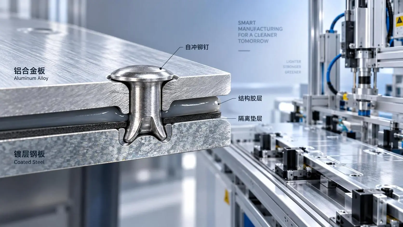
Selecting Metal Joining Methods for Aluminum-to-Steel Assemblies
Metal joining solutions for dissimilar metals: compare aluminum-to-steel fastening, bonding, hybrid, and thermal methods for corrosion-resistant, reliable assemblies.
Related News
- 00
0000-00
How to Select Vernier Precision Calipers for Tight-Tolerance Machining Inspection - 00
0000-00
How to Choose Metalworking Tools for Sheet Metal by Thickness and Forming Tasks - 00
0000-00
Metrology Technology Europe: Which Systems Improve Inspection Accuracy on the Line? - 00
0000-00
How to Choose Precision Measuring Instruments in North America for Tighter Tolerance Work - 00
0000-00
Specification-Oriented Articles on Precision Measurement: Which Parameters Matter Most?
Metrology Fellow
Weekly Insights
Stay ahead with our curated technology reports delivered every Monday.