
Industrial Assembly for Electronics: Key Controls for Reliable High-Volume Production





Reliable high-volume electronics assembly is not created by adding more inspection stations at the end of a line. It depends on controlling the variables that can alter a joint, damage a component, defeat electrostatic protection, or make a defect impossible to investigate later. The most important distinction is between a process that records activity and a process that proves conformity at the point where the product is built.
In industrial assembly for electronics, fastening torque, ESD discipline, material identity, solder-joint acceptance, fixture condition, operator authorization, and test results must work as one controlled system. A production line may achieve its planned cycle time while still producing latent failures if these controls are disconnected. Conversely, a technically sound line does not need to measure every possible variable; it needs to identify the few variables that directly affect product function, safety, compliance, and field reliability, then make them repeatable and traceable.
Start with the failure mechanisms, not the equipment list
Assembly controls should be derived from the product’s likely failure modes. This sounds elementary, but it is where many evaluations become distorted. A line specification may describe a torque tool, barcode scanner, ionizer, vision camera, and functional tester without explaining which product risks each device is intended to control.
Consider an electronics enclosure with a PCB, heat sink, display module, battery connection, and external connectors. The critical risks are different at each operation:
- A heat-sink screw can create insufficient thermal contact, PCB warpage, stripped threads, or excessive stress on a semiconductor package.
- A connector may appear fully seated while a terminal is backed out, a latch is not engaged, or a mating surface has been contaminated.
- A flexible circuit cable can be damaged by incorrect bend radius, poor ZIF connector engagement, or fixture interference.
- An ESD-sensitive IC may pass immediate functional test after an uncontrolled handling event but retain damage that reduces later-life reliability.
- A soldered assembly can meet a superficial visual standard while containing process conditions that require investigation, such as unusual voiding, insufficient barrel fill in a relevant application, or evidence of overheating.
The appropriate control is therefore determined by the failure mechanism, the severity of its consequence, and whether the defect can be detected after assembly. A cosmetic clip fit may only need presence confirmation. A safety-relevant fastener, thermal interface, high-current connection, or serialized calibration operation may require programmed tooling, sequence interlock, data capture, and defined reaction rules when the process falls outside tolerance.
Fastening control is more than a torque value
Fastening is frequently treated as a simple “torque reached” event. In electronics, that approach can be insufficient because final torque is only one indication of joint condition. The torque measured by a tool reflects friction under the screw head and in the thread, surface finish, lubrication, thread-forming behavior, joint compression, cross-threading, and the stiffness of the assembled stack. Two joints can reach the same final torque and still have materially different clamp loads.
This does not make torque control unhelpful; it makes application definition essential. The engineering specification should identify the fastener type, substrate or insert, target torque, acceptable tolerance, drive strategy, seating condition, required angle monitoring where appropriate, and rework policy. For thread-forming screws in plastics, for example, the process may need to distinguish thread engagement from final seating. A single torque threshold can fail to reveal cross-threading or damaged bosses.
Programmable DC electric tools are valuable where the joint is critical enough to justify closed-loop control and recorded results. Their practical advantage is not merely accuracy. They can enforce a selected program by model variant, prevent an operation from advancing after a fault, monitor torque-angle signatures, and link results to a unit serial number. Yet tool capability does not eliminate the need to validate the joint. The specified torque must be supported by joint testing, material behavior, service requirements, and an understanding of the permitted re-tightening or removal cycle.
For evaluating controlled fastening systems, the relevant questions are more precise than “Is torque traceable?”
- Is the torque range appropriate for the tool’s operating capacity, rather than concentrated near its lower limit?
- Does the controller detect conditions meaningful to the joint, such as early rundown termination, excessive angle, or abnormal seating torque?
- Is the program released by product configuration, not selected manually from an unrestricted menu?
- Are tool calibration, daily or shift verification, maintenance, and reaction to verification failure defined separately?
- Can a faulted cycle be associated with the physical unit, station, operator authorization, tool, program revision, and time?
ISO 5393 provides a recognized framework for testing the performance of power assembly tools. It should not be mistaken for proof that a particular electronic product joint is adequate. Tool performance qualification and joint-process validation are related but separate activities. The first confirms what the tool can deliver under defined test conditions; the second confirms that the selected strategy produces an acceptable assembly under real production conditions.
Traceability must preserve context, not just serial numbers
A serial number alone offers limited diagnostic value. Useful traceability allows an organization to reconstruct what was installed, how it was assembled, and what conditions governed the operation. The required depth depends on risk, regulatory obligations, contractual requirements, and the cost of a field investigation. It is not inherently necessary to collect every available machine signal.
For a controlled assembly process, a meaningful digital record may link the finished-unit serial number to PCB identity or lot, critical component lots, firmware or software version, test limits and result, torque program revision, torque-and-angle result, station identity, and any approved rework event. Where material shelf life or moisture sensitivity is relevant, the record may also need to establish that the component was released for use under the site’s defined material-control process.
The difficult issue is data integrity. A barcode scan can associate the wrong component with the right product if labels are duplicated, scanning is optional, or a station permits manual bypass without a controlled exception. Likewise, a torque controller can store a “pass” result that is not reliably linked to the unit actually receiving the fastener. Traceability design must address physical flow and system logic together: fixture identity, scan location, controlled routing, station lockout behavior, repair disposition, and synchronization failure handling.
Offline data collection introduces another risk. If production can continue while a controller or manufacturing execution interface is disconnected, the line needs a defined rule for local buffering, data reconciliation, and product disposition when complete records cannot be restored. Treating missing data as an administrative problem later can turn a contained communications fault into a large quarantine event.
ESD control is a production discipline, not an antistatic accessory
Electrostatic discharge protection is often reduced to wrist straps and conductive mats. Those are elements of a program, but they do not by themselves establish control. The relevant question is whether electrostatic-sensitive devices are protected through receiving, storage, kitting, transport, assembly, test, repair, and packaging.
ANSI/ESD S20.20 and IEC 61340-5-1 are widely used references for establishing and maintaining an ESD control program. Their application requires site-specific decisions based on device sensitivity, process environment, grounding architecture, packaging, personnel practices, and verification methods. A compliant-looking workbench is not proof of effective protection if components travel in unprotected trays, insulators remain in the electrostatic protected area without assessment, or personnel grounding checks are not connected to access control.
Three distinctions are particularly important in electronics assembly:
- Grounding versus charge control: Grounding personnel and conductive items is necessary, but insulating materials can retain charge and produce damaging fields. Where such items cannot be removed, ionization and material control may be necessary.
- Handling protection versus storage protection: A component can be safely handled at a controlled station and still be exposed during movement between kitting, repair, and test. Protective packaging must match the transport and storage risk.
- Program verification versus visual compliance: Wrist-strap testers, footwear checks, workstation resistance tests, ionizer performance checks, and audits should be based on the site’s documented program. A visual check cannot establish electrical performance.
ESD failures are especially difficult because immediate functional testing may not expose all damage. This is why ESD controls deserve the same attention as torque or solder-process records even when no failure is visible at the end of the line.
Component handling and fixture design can create defects before inspection begins
High-volume lines commonly use jigs, nests, vacuum pickups, feeders, and guided workstations to remove variation from manual handling. These aids are beneficial only when their contact surfaces, tolerances, and maintenance state have been considered as part of the process. A fixture can impose board flexure, obstruct a connector, scrape a conformal coating, trap debris, or mask an incorrect component orientation.
PCB support is a recurring concern. During connector insertion, screwdriving, press-fit operations, and testing, unsupported boards can bend. The concern is not limited to obvious cracking. Local strain can affect solder joints, ball-grid-array interconnects, ceramic components, and connectors. Fixture design should support the board near load points while avoiding contact with sensitive components, test pads, and areas that cannot tolerate compression. If support pins are adjustable, their configuration becomes a controlled setup variable rather than a casual operator adjustment.
Material presentation matters as much as fixture geometry. Similar-looking connectors, screws, labels, and cable assemblies create predictable mix-up risk. Physical segregation, keyed trays, vision-supported confirmation, scan validation, and pick-to-light controls are useful only if they address the actual ambiguity. A scan that validates a broad family number will not prevent installation of the wrong length, revision, polarization, or regional variant.
Where moisture-sensitive electronic components are assembled by soldering, material handling must also align with the applicable moisture-sensitivity classification and the organization’s defined floor-life controls. Improvised drying or uncontrolled exposure cannot be treated as equivalent to a documented baking and handling procedure.
Inspection should verify what the process cannot guarantee
Inspection is most effective when it is assigned to uncertainty that remains after process control. It is inefficient to rely on end-of-line visual inspection to compensate for an uncontrolled fastening operation or a weak component-identification system. A camera can verify visible presence and orientation; it cannot establish an invisible clamp load or prove that a scanned component was physically installed.
For soldered electronic assemblies, IPC-A-610 is commonly used for acceptance criteria, while IPC J-STD-001 addresses requirements for soldered electrical and electronic assemblies. These documents should be invoked with the applicable revision, class, customer requirements, and any product-specific acceptance criteria. Merely stating “IPC compliant” is not sufficiently precise because acceptance class, process requirements, and contract language can change the required interpretation.
Inspection method should reflect defect accessibility:
The test strategy should also control test software, fixtures, limits, and version changes. A functional test record is meaningful only when it identifies the test revision and limits used. If a limit is altered, the effect on units tested before and after the change must be traceable. This is particularly important for products with firmware-dependent tests or multiple hardware revisions sharing a common production route.
Operator guidance should prevent errors, not document them afterward
Digital work instructions, pick confirmation, torque interlocks, and guided repair screens can reduce dependency on memory. Their effectiveness depends on how they handle variation and exceptions. A work instruction that displays the same generic sequence for all variants can create confidence without controlling configuration. A bypass function that is broadly available can undermine an otherwise well-designed interlock.
Good operator guidance is specific enough to control the task but not so burdensome that routine work becomes dominated by acknowledgements. It should present the correct product revision, component identity, tool program, fixture configuration, inspection point, and escalation condition at the time they are needed. Critical warnings should require a defined disposition rather than a simple confirmation click.
Rework requires equal discipline. Removing and reinstalling a fastener, replacing a connector, touching up a solder joint, or rerunning a test may alter the product’s process history. The system should distinguish authorized repair from uncontrolled repetition, record the reason and disposition, and apply any required retest. Rework is not automatically defective practice; unbounded rework without technical limits or traceable authorization is the concern.
Evaluate the control plan as an integrated system
The strongest indicator of a mature high-volume assembly process is consistency between the product risk analysis, work instructions, equipment settings, maintenance controls, inspection criteria, and production records. A technical review should be able to trace a critical requirement in both directions: from a design risk to the station control that prevents or detects it, and from an abnormal production record to the specific unit and disposition affected.
That review should deliberately test realistic disruptions: a wrong component scan, a tool verification failure, a lost network connection, an ESD access-check failure, a fixture changeover, a rejected torque cycle, or a test-limit revision. These events expose whether the line merely captures data under normal conditions or actively prevents uncontrolled product from moving forward.
Reliable electronics production at volume is therefore less about a single advanced tool than about closure between engineering intent and shop-floor execution. Precision fastening, ESD protection, controlled handling, in-line verification, and traceable workflows each address different failure paths. When their boundaries and exception rules are defined clearly, the line can sustain output without making quality dependent on final inspection or individual memory.
Related News

Laser vs. Resistance Spot Welding: Which Fits Automotive Body Assembly?
Choosing welding technology for automotive body assembly? Compare laser and resistance spot welding on joint access, quality, cycle time, and cost to find the right fit for your production line.
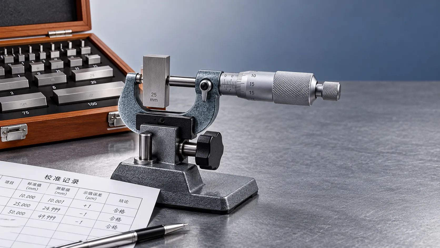
Choosing a High-Precision Measuring Instrument Supplier: Calibration and Support
Choose a high-precision measuring instruments supplier with confidence. Discover how to verify calibration, compare support, and control lifecycle costs before you buy.
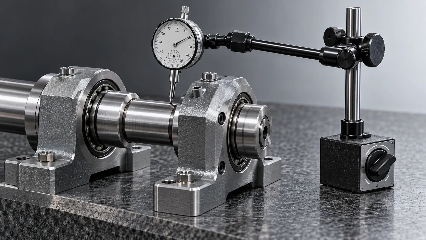
What Defines Craftsmanship in Metalworking? Fit, Finish, and Precision
Discover what defines craftsmanship in metalworking: fit, finish, and precision. Learn how to spot quality, assess suppliers, and choose parts that perform reliably.
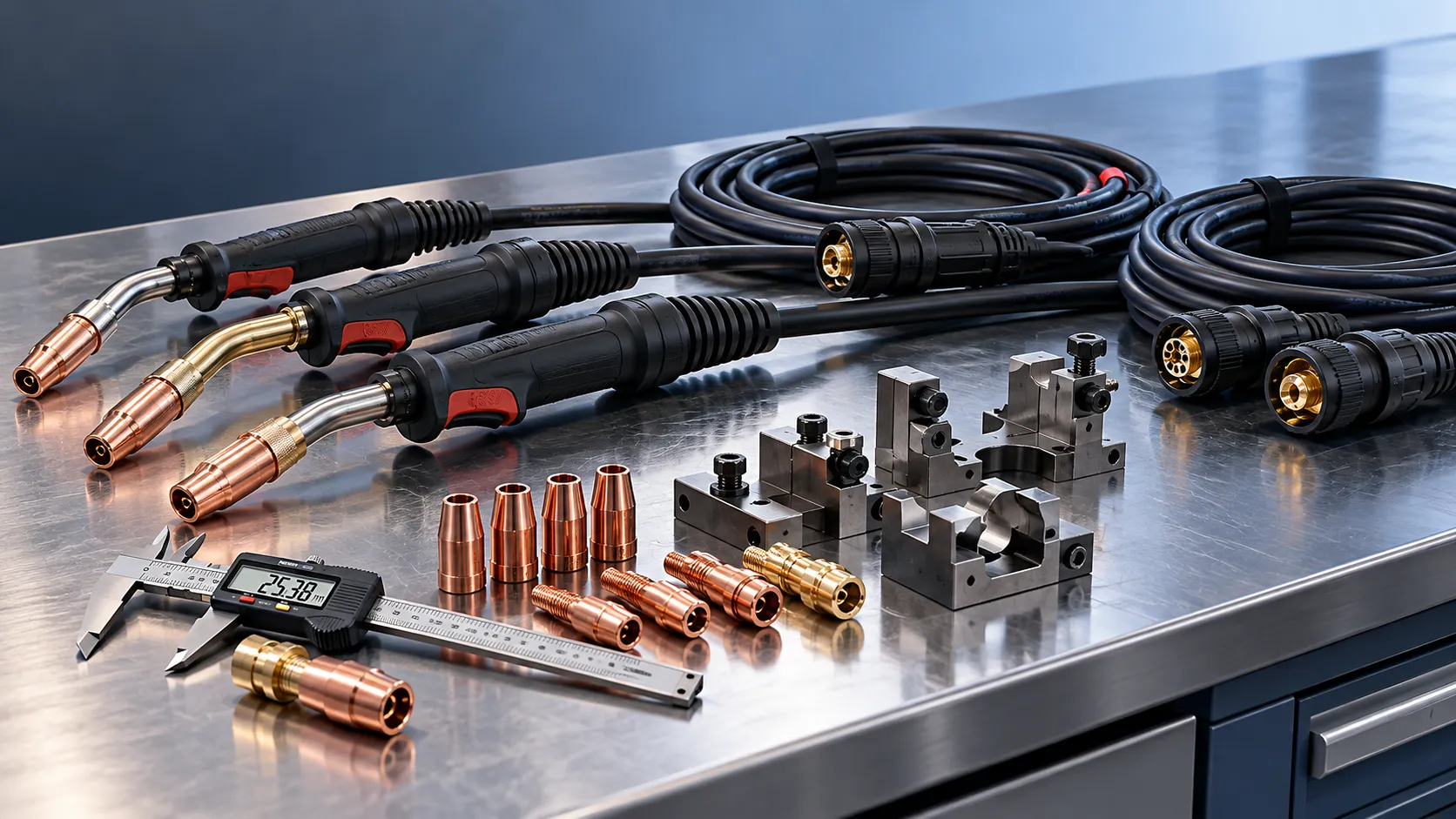
Choosing a Welding Tools Manufacturer: Quality Checks Before a Bulk Order
Choosing a welding tools manufacturer? Discover essential quality checks, sample tests, and inspection terms to reduce bulk-order risks and buy with confidence.
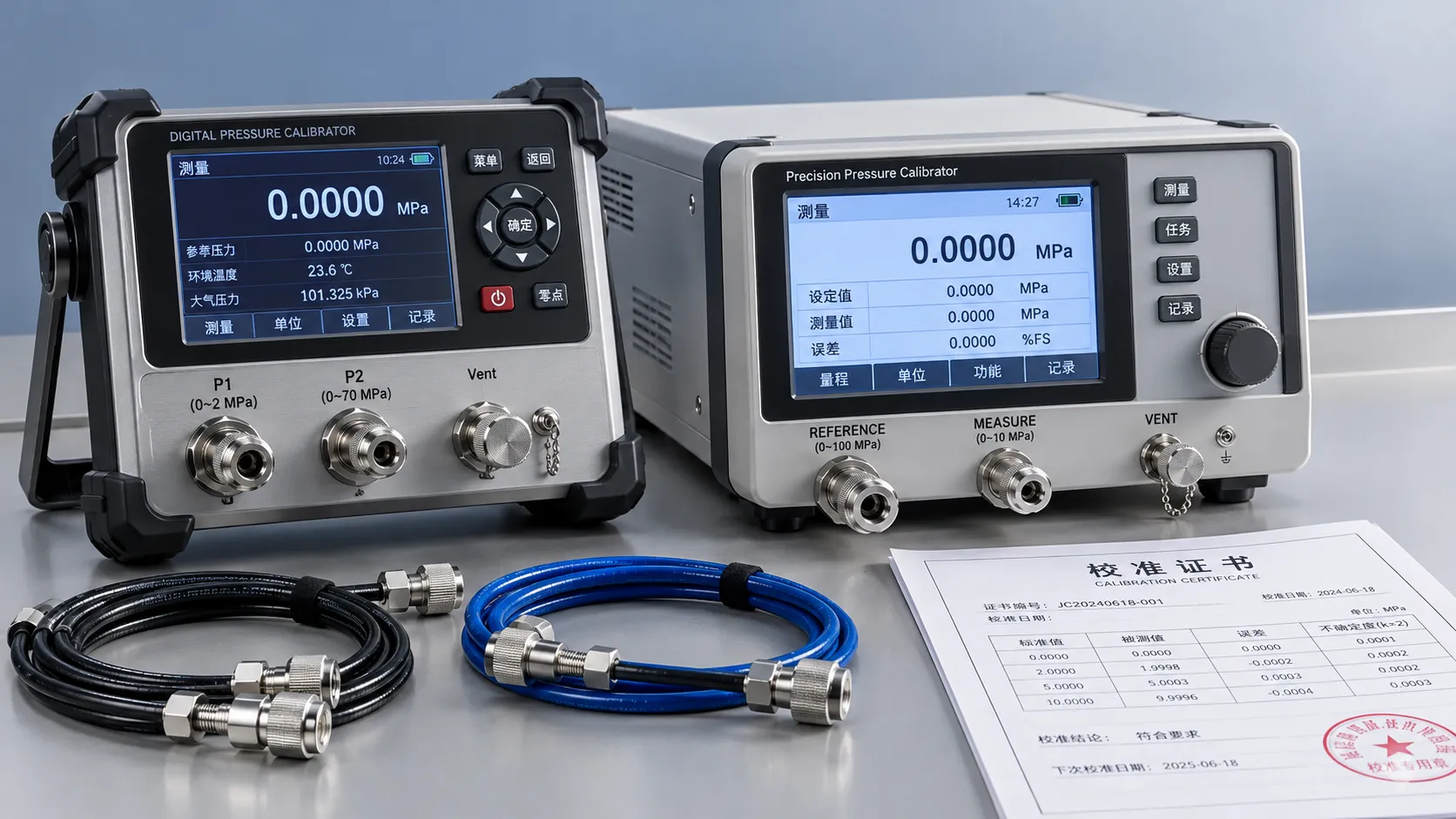
How to Compare Calibration Tools: Range, Uncertainty, and Traceability
Explore product comparison resources for calibration tools. Compare range, uncertainty, and traceability to choose confidently and support defensible measurement decisions.
Choosing Industrial Metrology Tools: Matching Measurement Uncertainty to Tolerances
Improve industrial tool selection for metrology by matching measurement uncertainty to tolerances. Learn how to reduce inspection risk and choose equipment with confidence.
Torque System Suppliers: How to Assess References for Assembly Projects
Explore supplier and solution references torque systems buyers should verify. Assess assembly fit, traceability, and support to reduce risk and choose with confidence.

Equipment Application Guidance for the Middle East: Managing Heat and Dust
Explore application guidance Middle East teams can use to manage heat and dust, protect welding equipment, batteries and precision tools, and reduce downtime. Get practical tips.
Choosing a Handheld Laser Welding Supplier: Weld Trials, Training, and Service
Choose a handheld laser welding supplier with proven weld trials, safety training, and reliable service. Learn what to verify before buying to reduce downtime and protect your investment.
Related News
- 00
0000-00
Equipment Application Guidance for the Middle East: Managing Heat and Dust - 00
0000-00
Choosing an Industrial IoT Platform: Key Criteria for Legacy Equipment - 00
0000-00
How to Select High-Precision Measuring Instruments for Tight-Tolerance Production? - 00
0000-00
How Do Advanced Manufacturing Methods Improve Batch Consistency? - 00
0000-00
Can Industrial IoT Torque Data Reduce Assembly Defects?
0000-00
Prof. Marcus Chen
Weekly Insights
Stay ahead with our curated technology reports delivered every Monday.